In this project, we will learn about Knock Sensor or Vibration Sensor (sometimes called as Tap Sensor). In the process, we will see what are components of a Knock Sensor, how a Knock Sensor works and finally how to Interface a Knock Sensor with Arduino.
Outline
ToggleA Brief Note on Knock Sensor
A Knock Sensor or a Vibration Sensor is a simple device that detects vibrations or shocks from knocking or tapping it. It is basically an electronic switch which normally open. When it detects any shock or vibrations, it closes (for that moment and returns back to its default open position).
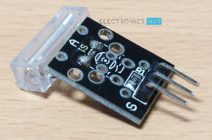
Several Knock Sensors are available in the market and the cheaper ones are called KY-031 Knock Sensors. The following image shows the Knock Sensor Module used in this project.
Components of a Knock/Vibration Sensor
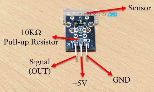
A typical knock sensor consists of the main sensing element, which is a conductive vibrating spring, a Resistor and three Pins.
The three pins of the Knock Sensor Module are GND, +5V and S. The following image shows the components of a Knock Sensor Module as well as the pins on it.
Schematic of Knock Sensor
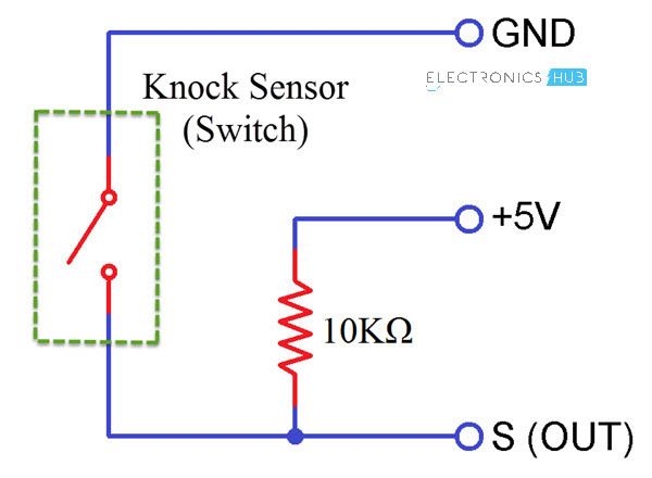
In order to understand how a Knock Sensor Module works, I thing knowing its schematic is important. The following image shows a simplistic representation of the schematic of a Knock Sensor Module.
How does a Knock Sensor Work?
If you take a look at the schematic of the knock sensor, it basically consists of a switch and a resistor. The Vibrating Spring is represented as a switch here.
The output pins of the sensor (which is connected to one end of the switch) is pulled HIGH with the help of a 10KΩ Pull-up resistor.
Under normal condition i.e. when there is no shock or vibrations, the output of the Knock Sensor is HIGH.
When the sensor detects any vibrations or shocks, the vibrating spring i.e. switch closes and hence the output of the sensor (at the output pin) will become LOW.
Also see BEST ARDUINO SENSOR KITS
Interfacing Knock Sensor with Arduino
Now that we have seen the components of a knock sensor and how a typical knock sensor works, let us proceed with interfacing a knock sensor with Arduino.
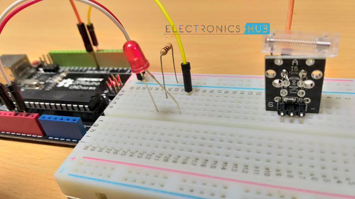
I have designed a simple circuit using Arduino, Knock Sensor and an LED where the LED is turned on by Arduino when the knock sensor detects any vibrations.
Also the information of the knock sensor (knock or no knock) is displayed on the Arduino IDE’s serial monitor.
Circuit Diagram for Interfacing Knock Sensor with Arduino
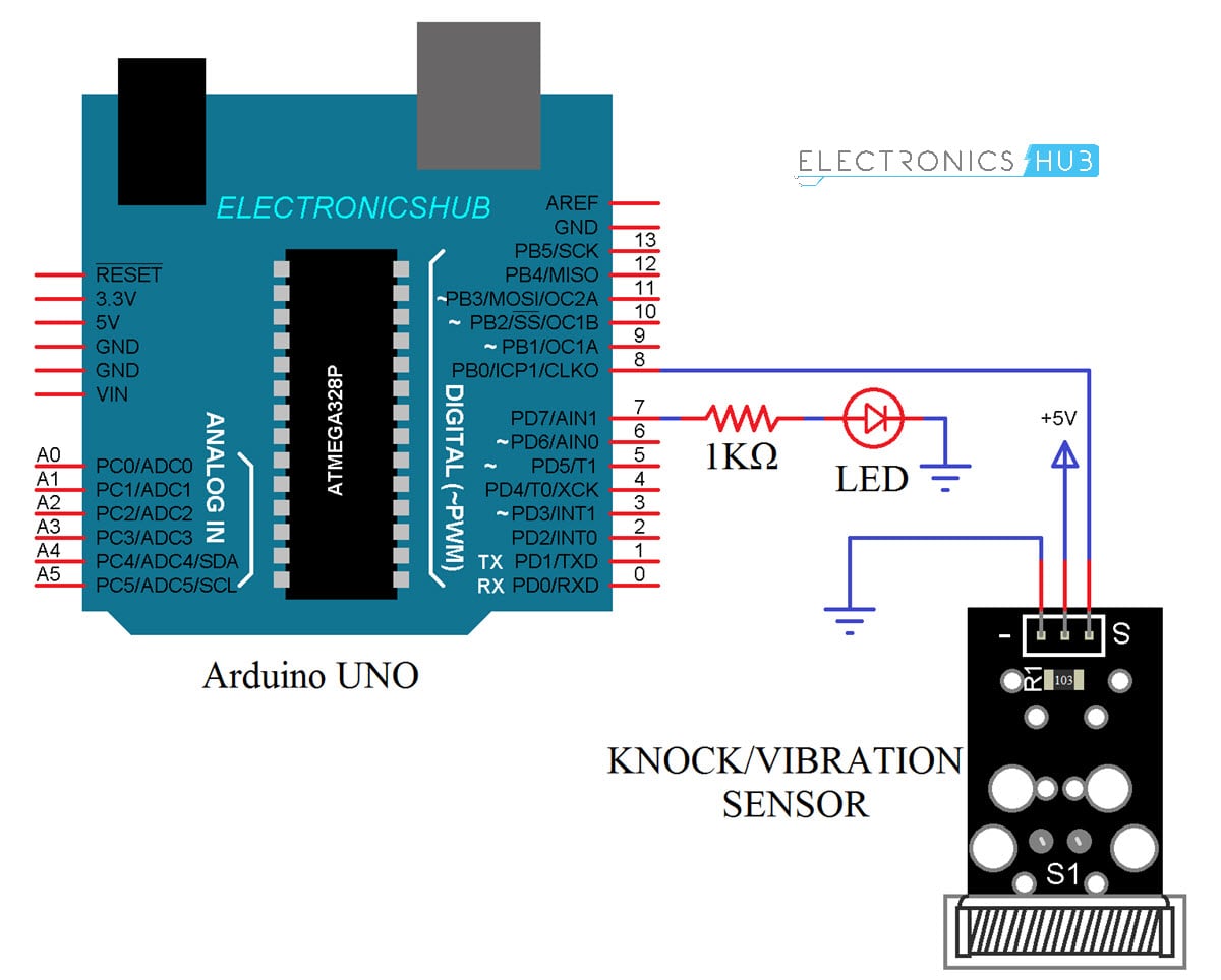
The following image shows the circuit diagram of Interfacing a Knock Sensor with Arduino UNO.
Components Required
- Arduino UNO
- Knock Sensor Module
- 1KΩ Resistor
- LED
Circuit Design
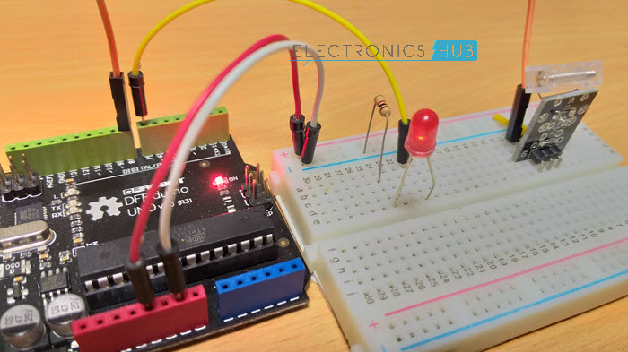
The design of the circuit for Arduino Knock Sensor interface is very simple. Connect the Supply and GND pins of the Knock Sensor to +5V and GND pins of Arduino.
Then connect the OUT (S) pin of the sensor to Digital I/O pin 8 of Arduino UNO. Finally, an LED is connected to Pin 7 of Arduino UNO through a 1KΩ current limiting resistor.
Code
The code of interfacing knock sensor with Arduino is given below.
Working
Make the connections as per the circuit diagram and upload the code to Arduino. Fix the knock sensor to a door and knock on the door.
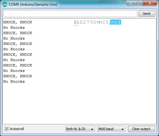
If the vibrations are sufficient enough for the sensor to detect, the OUT of the sensor becomes low for that moment. This is detected by Arduino and it turns ON the LED for a second.
The results are also displayed on the serial monitor.
Conclusion
As per the experiments conducted at ElectronicsHub, we found that the Knock Sensor is not a very sensitive device. It doesn’t detect small knocks or taps but rather requires hard vibrations for it to detect.
Using this type of knock sensor for experimenting with some security applications like Door Knock Monitoring Systems is fine but using it as a serious sensor in a real time application is not suggested.
Applications
The main purpose of the Knock Sensor is to detect vibrations or shocks. Hence, the main application of such sensor can be in Door Knock System, where when a door is knocked, a notifications (like a light or a buzzer) can be activated.

