Water Level Controller using 8051 Microcontroller project will help in automatically controlling the water motor by sensing the water level in a tank. This article explains you how to detect and control the water level in an overhead tank or any other container. This system monitors the water level of the tank and automatically switches ON the motor whenever tank is empty.
The motor is switched OFF when the overhead tank or container is FULL. Here, the water level of the tank is indicated on LCD (Liquid crystal Display). Using this system, we can avoid the overflow of the water.
We have already seen How water level indicator circuit works using AVR Microcontroller in the earlier post. But, here we are designing the circuit which is used to detect and control the water level automatically in overhead tank using 8051 microcontroller.
Outline
Toggle- Water Level Controller using 8051 Microcontroller
- Construction and Output Video
- Water Level Controller using 8051 Circuit Principle
- Water Level Controller using 8051 Microcontroller Circuit Diagram
- Components Required for Water Level Controller using 8051 Microcontroller
- How to Design Circuit for Water Level Controller using 8051 Microcontroller?
- Algorithm for Water Level Controller Circuit
- Water Level Controller using 8051 Circuit Simulation Video
- How to Operate Water Level Controller Circuit using 8051 Microcontroller?
- Water Level Controller Circuit Advantages
- Applications of Water Level Controller Circuit using 8051
Water Level Controller using 8051 Microcontroller
In this system, water sensing can be done by using a set of 4 wires, which are placed at different levels in tank. DC supply probe is placed at the base of the tank.
Construction and Output Video
Water Level Controller using 8051 Circuit Principle
This system mainly works on a principle that “water conducts electricity”. The four wires which are dipped into the tank will indicate the different water levels. Based on the outputs of these wires, microcontroller displays water level on LCD as well as controls the motor.
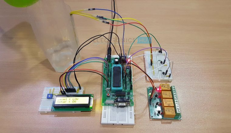
Initially when the tank is empty, LCD will display the message LOW and motor runs automatically. When water level reaches to half level, now LCD displays HALF and still motor runs.
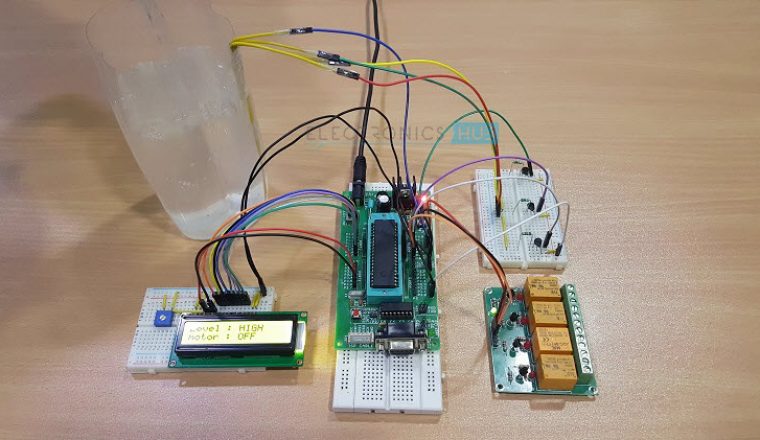
When the tank is full, LCD displays FULL and motor automatically stops. Again, the motor runs when water level in the tank becomes LOW.
Water Level Controller using 8051 Microcontroller Circuit Diagram
Components Required for Water Level Controller using 8051 Microcontroller
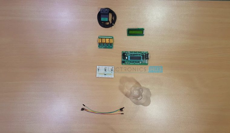
- AT89C51 Microcontroller (or any 8051 based Microcontroller)
- 8051 Programmer (Programming Board)
- 11.0592 MHz Quartz Crystal
- 2 x 33pF Capacitor
- 2 x 10KΩ Resistor (1/4 Watt)
- 10µF Capacitor
- Push Button
- 1KΩ x 8 Resistor Pack (for Pull – up)
- 16 x 2 LCD Display
- 5V Relay
- 4 x 2N2222 (NPN) Transistors
- DC Motor (for demonstration)
- 10KΩ Potentiometer
- 1N4007 PN Junction Diode
- Programming cable
- Connecting wires
- Power Supply
- Keil µVision IDE
- Willar Software (for burning code)
- Proteus (for circuit diagram)
How to Design Circuit for Water Level Controller using 8051 Microcontroller?
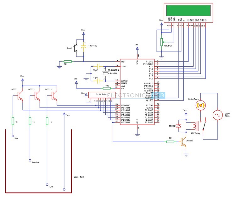
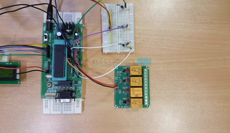
The heart of the Water Level Controller using 8051 Microcontroller project is the AT89C51 Microcontroller. The water level probes are connected to the P0.0, P0.1 and P0.2 through the transistors (they are connected to the base of the transistors through corresponding current limiting resistors). P0.0 for LOW level, P0.1 for HALF Level and P0.2 for HIGH Level.
The Collector terminals of the Transistors are connected to VCC and the Emitter terminals are connected to PORT0 terminals (P0.0, P0.1 and P0.2).
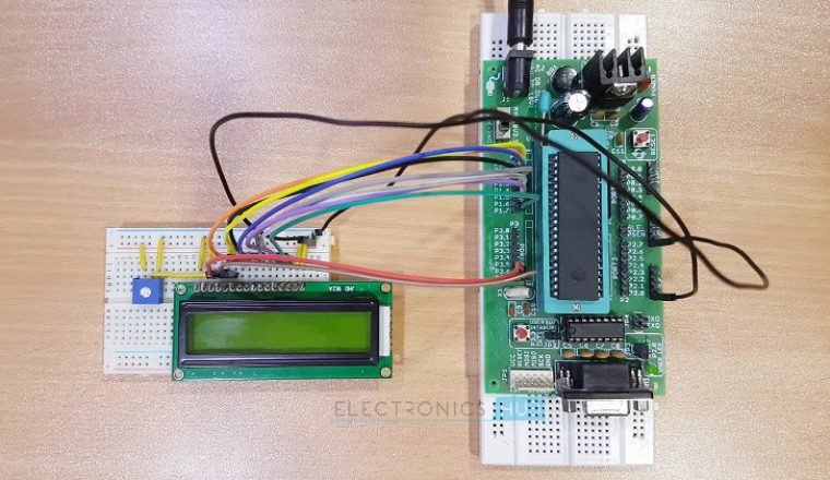
PORT1 of the microcontroller is connected to the data pins of LCD and the control pins RS, RW and EN of the LCD Display are connected to the P3.6, GND and P3.7 respectively.
For demonstration purpose, we have used a simple DC Motor Pump. It is connected to the Relay and the input to the relay is fed from P0.7 through a transistor.
Related Post: Also read the interesting concept about How water level alarm circuit works using 555 Timer.
Algorithm for Water Level Controller Circuit
- First configure the controller pins P0.0, P0.1 and P0.2 as inputs and P0.7 as output.
- Now, initialize the LCD.
- Continuously check the water level input pins P0.0, P0.1 and P0.2.
- If all the pins are low, then display tank as “EMPTY” on the LCD and make P0.7 pin HIGH to run the motor automatically.
- If the level is low i.e. if P0.0 is HIGH, display the water level as “LOW” and continue to run the motor.
- A HIGH pulse on the pin P0.1 indicates that water has reached half level. So, display the same thing on LCD and run the motor normally.
- If P0.2 is HIGH, then the water level in the tank is FULL.
- Now, make the P0.7 pin as LOW to turn off the motor automatically.
Water Level Controller using 8051 Circuit Simulation Video
DOWNLOAD PROJECT CODE
How to Operate Water Level Controller Circuit using 8051 Microcontroller?
- Initially, write the program for Water Level Controller in Keil µVision IDE and generate the .hex file.
- Burn the program (.hex file) to the microcontroller using external programmer and Willar Software.
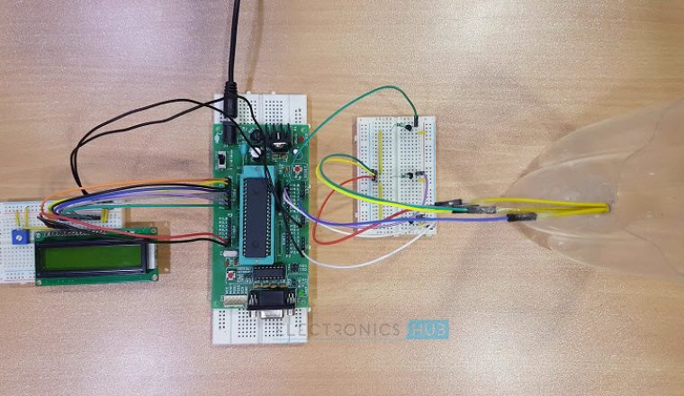
- Now give the connections as per the circuit diagram.
- While giving the connections, make sure that there is no common connection between AC and DC supplies (if you are using an AC Motor)
- Place the 4 water level indicating wires into the small tank (3 probes for three different levels and fourth one for common supply)
- Switch on the supply. Now, the motor will run automatically as there is no water in the tank. (It will turn on even if the water level is LOW).
- Now pour the water, when it reaches LOW level, then LCD displays LOW.
- For middle level, it will display as HALF on the LCD.
- Still if you pour the water, then the water level reaches full and the LCD displays FULL and also the motor is turned OFF automatically.
- Switch off the motor supply and board supply.
Get an idea about How to Interface 7 Segment Display with 8051 Microcontroller
Water Level Controller Circuit Advantages
- Human effort is reduced as the system controls the motor automatically based on the water level.
- This system consumes less power.
- Simple and more reliable.
[Also Read: How To Make an Adjustable Timer ]
Applications of Water Level Controller Circuit using 8051
- Used in big buildings where the manual monitoring is difficult.
- Used in industries to control the liquid level automatically.


92 Responses
can i get the source code for this project ? please send me the source code to my email. I want to make the same project like this using at89s52.
Hi, did you ever get the source code for this project? If so, please share I like this project a lot too and want do it as well
plz send simulation file
Does the project code in the link support only the LCD or the motor also?
Click on above link downloard source code
in this source code the working of lcd is fine but relay is not turning on. i think the programming of motor is wrong. plzz help me.
i want the source code for the 8051 microcontroller
Not working when I pressed the download code link.
I’m making the same project and i need the code for it. It is personally a very useful product for me.
I like to make this project
I wd like one for my house
I wd do the same one
I want to do this nd want install I in my home.. Please give me source code and total project cost.
That is great..Source code is already provided in the article.Please go through it..If you have any further clarifications you can contact us..
i have burn the code into the software but why i cant run the circuit?the code should be done in its software or we just can copy & paste in Dev C++? Pls answer me. This project need to be done before wednesday :(((
Try to copy paste the code in Keil Software and create a hex file then burn to the controller..
I have tried running it in keil but I still gives me error.can you please send me the hex file?..my email is skuulfeez@gmail.com
The motor is not running with this source code. Please help!
I have to make project related to microcontroller. I like the idea of this project & I want to make this project for my course.
So I need the source code of this project, plz send me the source code as soon as I start my working in this project.
We have already provided project code in the article.Please go through the article..
Will the Current pass into our body if we touch the water
No problem you will not get any shock
I real need this source code because i have three simtank when the water is full in these tank they tend to fall down plz help me
hello, iam iddham from Malaysia, an engineering student, as you can see , currently its the monsoon period in Malaysia, which causing flood in certain area, most at the east side of Malaysia, my objective here, to create a water indicator level detector so that it maybe can help the people here to indicate the water level earlier and can make early move and maybe save more lives.
so i see that this project maybe useful but i need your help to complete the project. i have little knowledge in embedded system such as, runninglight, loop, adcon, timer .
so can you help me ? in theme of the hardware and program code?
email : iddhamshahlee@gmail.com
What about the electrolysis that takes place in water. that is one of the major problem found which corrodes teh sensors.
Please I need the project code… I want to make the same project for my industrial training defense in school…it’s urgently needed…
Hi,
I want to do this project for my final year project. i see that this project is suitable for my field of engineering i am doing now. Please email me the source codes for this project. Your help is highly appreciated..
Please go through the article,we have already uploaded the code..
i just wants to show to my students how micro-controller is used in instrumentation applications?
why had n’t you reply the email said that there is an electrolysis appears in the water tank.can u give a good answer for that problem?
it is so nice but how can i install it in my home without any labour
i want to do this project, so i want this project programe . so please send the code to my mail.
Sir send me code of water level indicater
i am intrested in this project and i need source code,should give me them so that i can do it as my final work?
Hi sir i m persuing diploma in ECE. So i have to know about the source code for this project.Because i m going to made my major project which is quite simillar to this pls giv me source of this projct.THANKYOU
hello sir, m student of BE. I want source code of this PROJECT becuase i am make this project .Send it to my email-id.
i want to do the same project using 89s52 micro controller so please send me the code
where is the 10K Pot used in the whole circuit
10 k pot is used for LCD display to adjust its brightness
can someone help me how to program the code into the mcu at89c51?? is there a possibility that it can be programmed using pickit2?? thnx for the reply…
can i please get source code for this project…….i want to do same project .
Code is already Uploaded Please go through the article..U need to download keil to open these files..
.Can I get source code for this project I am interested to do this project for my final year project.
I would like to same project and add more function to it.
The application is same..
it is a fantastic project i like it. would you send the source code for these project since i am doing asimilar project using 8086 micro controller.
Download the code from post..
hi, i am trying to do this project using 89S51, never done this so please guide me somehow , is the code different from 89c51 (gives me an error about header missing) . what program should i use , i;ve tried with kel and arduino –compliling with errors .Thank you (mikem1907@yahoo,com) , also i use an aspusb 2.0 programmer
can you please me the code file or full code here?
I am working on this project lcd does not show any msg why this error is obtain please help mi
It’s a wonderful project. I am working on a project where I need to sensor the level of water. I would like to know how those 4 wire inside the water works. Could you please explain? Thank you in advance.
please can i get the circuit diagram of water level controller which, the motor should run when the motor switch is on. and it should be off automatically when the tank is full.
can i hav the code which is in assemby langauge plz
can i get source code using assembly level language for this project
I need assembly language code for this project..Can’t find asm file here..
I am making the project for my household motor.
I have a query related to water tank sensors.
In water tank you have placed simple wires or sensors?
If it is sensors, Which sensors have you used?
No sensors were used in this project.Only wires were used.
can i have full report about this project?
I have prepared the circuit as explained by you. I am facing below problem.
My circuit works perfectly if my body part didn’t have any contact with water.
When my body part touches the water whole circuit behaves strangely. It stops working, then I have to press the reset of controller. I think when body part touches the water, sensing probes creates the voltage fluctuations and whole circuit mechanism is failing.
Please provide the advice.to overcome this issue.
Hello sir motor is not running in this project
i have pasted the code in keil software and built it but i have got 0 errors but 1 warning tell me the solution of this problem ?
i have pasted the same code in keil software i got 0 error but 1 warning so tell me about the solution of this problem?
hi, i am doing this as my lab project.we are doing the same thing in arduino .we are facing the problem .its not working.can you help us how to write code in arduino
It is very good project. I want to work this project please give the program and their code my email addressed
its very good
Hi can I get the proteus simulation for this project? Thanks a lot. Great project by the way
please send me source code of this project
I make same with different UC
through your code i will the idea about this
i would be very glade if you could kindly send me the code
which burner have you guys used????
Why motor is not running when the tank is empty ?
is that v1 (vsine wave) supply is really required between motor and relay???or will that circuit works without that connection???whwt is the use of that??plz rply fast…
Motor is not running with the above source code… what changes do we have to make
Is the source code is correct are not while I m executing the project in Proteus all the working but the relay switch is not changing its position why it happenes like that I want to submit this project by Monday plzz tell me the solution for this problem as soon as possible.
I got the source code but it doesn’t have .hex file, i attempt to create a .hex file but i can’t.
is any one who create or got a .hex file pls tell me , i need your help…
Show the full connection wile simulating in protius motor is not running.
how to connect with power supply show it.
why are you using transistor? suppose transistor is replaced by a other component what’s going on?
could u plz help me in making my fyp with a further modification in above project by controlling the voltage of water pump
hello,
i want to know did the project used DC motor or AC motor to operate?
thanks you
Will I get the output by executing the circuit given in the article….Can u plzz tel me
this one is good project… but i want wirless waterlevel controller if possibel then send me on my email ☺
Source code need some edition there are 2 lines which is unnecessary …
LCD not work because this ckt diagram is not complete and proper
In my case I m able to run this project only on developer board but due to incomplete ckt diagram I face difficulties in making of this project
Plzz help me
hello,
This project is good.
I would like if there is any microcontroller based project based on solenoid valve closing and opening for respective litres of water to fill the tank.
plz send me any link or source file.
Hey,
Just read the article and got instantly hooked but the source code isn’t showing gives me a site can’t be reached
Hi..
thanks for your info.
This is one of the good project. Thanks bro
How to use the relay circuit for dc motor operation.
In the circuit diagram, just replace the motorpump with a DC Motor and AC supply with DC Supply. Make sure that the voltage rating of the relay will support the DC Motor you want to use. I suggest you not to control a DC Motor with relay as all you can do is switch the motor ON or OFF. Go with a Motor Driver like L298N (for example). Using this, you can control the speed of the motor as well as the direction of the rotation.
how to use d relay circuit for dc motor operation
Another good tutorial, any idea about the probe material?, anyone?
how much taka need for this project, CAN YOU TELL ME
Dear how can i do this by using pic16F877A microcontroller and its wiring diagram
Information is very nice
Hey please can i get the source code for the above project…i need it for a mini-project that i am making
Would someone please help me with the project code
Hi please share the project code