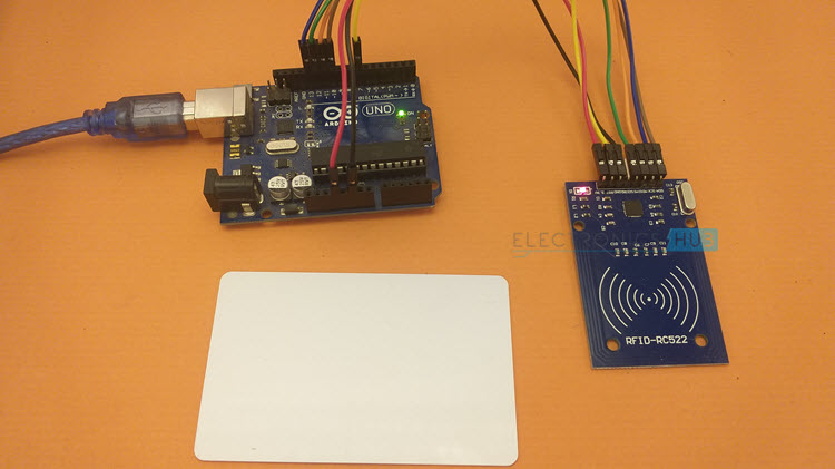
In this tutorial, we will learn how to Interface RC522 RFID Reader with Arduino and use MIFARE Classic 1K RFID Card and Key Fob. The RC522 Module is based on NXP’s MFRC522 RFID Reader / Writer IC operating at 13.56 MHz. We will learn how the Arduino RC522 RFID Card Reader Interface works with a couple of test codes.
Outline
ToggleIntroduction
If you are following the motor laws in some countries, Electronic Toll Collection (ETC) systems are becoming mandatory. In ETC, the toll charges for the vehicle are automatically deducted as soon as the vehicle arrives at the booth. There is no need to pay cash or wait in queue.
This is one brilliant application of RFID or Radio Frequency Identification System. You might have seen other similar applications of RFID like contact-less payment and automatic check-out system in super markets, access control in banks and offices, tracking of goods in warehouses etc.
All these and many other applications are using the RFID Technology.
Also Check: Interfacing Sound Sensor with Arduino
A Look Back at RFID
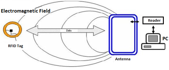
RFID is short for Radio Frequency Identification. As the name suggests, RFID uses electromagnetic waves in radio frequency to transfer data. A simple RFID System consists of just two components: an RFID Transponder and an RFID Transceiver.
The RFID Transponder is usually a Card, Tag, Key Fob or a Sticker while the RFID Transceiver is a reader / writer device capable of reading and writing data from / to an RFID transponder.
Additionally, the RFID reader has an Antenna to emit high frequency EM Waves. The RFID Tag also contains an Antenna and an IC to store the data. When the RFID Tag comes in proximity of the high frequency EM Waves from the reader antenna, its antenna energizes the IC in the tag.
The IC then acknowledges with the information stored in it with a return radio signal.
A Brief Note on RC522 RFID Module
With all the introduction, let us dive into the important component of this project, the RC522 RFID Module. It is an inexpensive RFID Reader Module based on MFRC522 RFID IC from NXP.
The MFRC522 IC supports a wide variety of RFID Tags like MIFARE 1K, MIFARE 4K, MIFARE Mini and other ISO / IEC 14443 protocol based cards and tags.
It operates at 13.46 MHz frequency and the operating range is up to 50 mm. The MFRC522 IC supports three types of serial communication with the host (Microcontroller like Arduino). They are:
- SPI
- UART
- I2C
Contents of the Kit
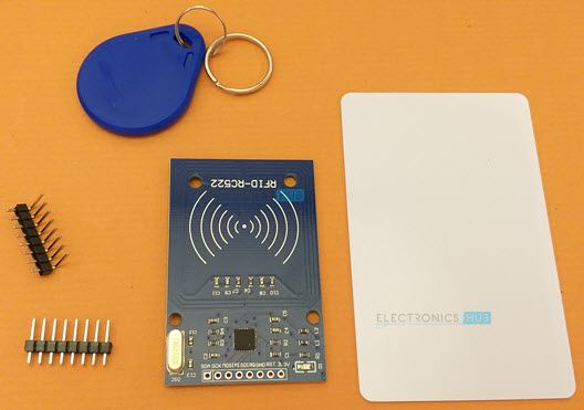
The RC522 RFID Reader kit consists of the RC522 RFID Reader Module, RFID card, RFID Key Fob and couple of male headers to solder. Both the RFID Tags i.e., RFID Card and RDIF key fob in the kit are compatible with MIFARE 1K tags (they both have 1 KB of memory).
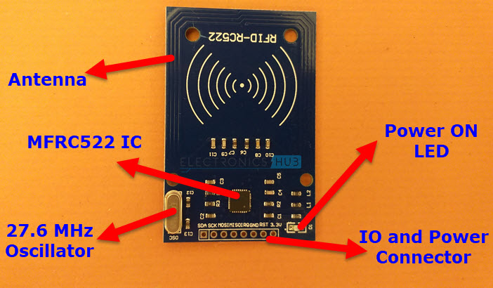
The RC522 RFID Reader Module consists of the MFRC522 IC, a 27.12 MHz Crystal Oscillator, an Antenna embedded on the PCB and supporting passive components to emit 13.56 MHz electromagnetic field.
An important thing to remember is that the MFRC522 IC operates at a supply voltage of 2.5V to 3.3V but the communication pins are tolerant to 5V. So, the power supply voltage should be 3.3V, but you can connect the data pins to Arduino directly.
Pinout of RC522
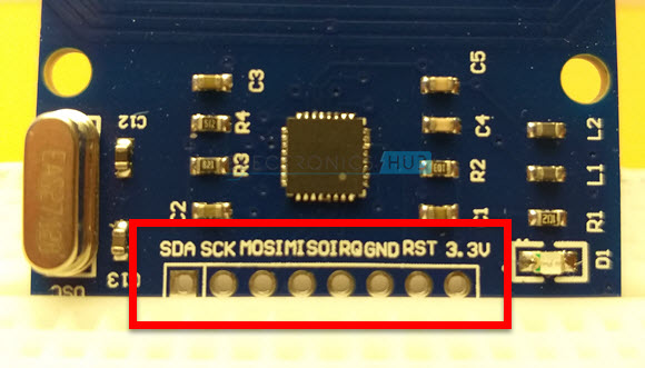
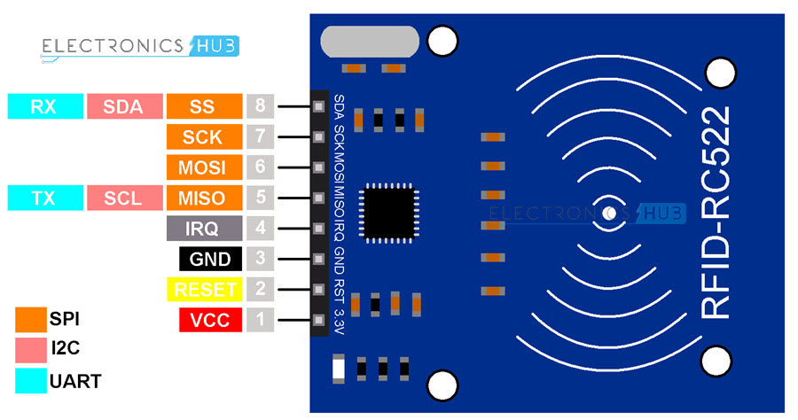
The following image shows the pinout of RC522 RFID Reader Module. Even though we are going to use SPI Interface for connecting with Arduino, I showed UART and I2C pins as well.
|
Pin Number |
Pin Name |
Description |
|
1 |
VCC | 3.3V Supply Pin |
| 2 | RST |
Reset Pin. When LOW, resets the MFRC522 IC. |
|
3 |
GND | Ground |
| 4 | IRQ |
Interrupt Pin. To interrupt host device (Microcontroller). |
|
5 |
MISO / SCL / TX | This pin acts as MISO in SPI, SCL in I2C and TX in UART |
| 6 | MOSI |
SPI MOSI Pin. |
|
7 |
SCK | SPI Clock Pin. |
| 8 | SS / SDA / RX |
This pin acts as SS in SPI, SDA in I2C and RX in UART |
Terminology
There are two terms often used with MFRC522 RFID Module’s documentation. They are:
- PCD
- PICC
PCD is short for Proximity Coupling Device. It is nothing but the RFID Reader Module based on the MFRC522 IC.
PICC is short for Proximity Integrated Circuit Card is an RFID Card or Tag built using ISO / IEC 14443 Protocol like MIFARE or NTAG.
Arduino RC522 RFID Card Reader Interfaarduino megace
Now that we have seen a little bit about the MFRC522 RFID Reader IC and RC522 RFID Reader Module, let us now proceed with Arduino RC522 RFID Card Reader Interface. As mentioned earlier, MFRC522 supports SPI, UART and I2C interfaces.
But SPI is the fastest of the three with data rates up to 10 Mbit/s. So, in this project we will see how to interface RC522 RFID Module with Arduino using SPI.
Coming to Arduino’s SPI, instead of using software SPI with bit-banging, we will use the hardware SPI. This means that SPI pins in Arduino are fixed (at least for MOSI, MISO and SCK).
The following table shows all the connections between Arduino and RC522 RFID Reader Module.
|
RC522 RFID Reader |
Arduino UNO / Nano | Arduino Mega |
| RST | 9 |
5 |
|
SS |
10 | 53 |
| MOSI | 11 |
51 |
|
MISO |
12 | 50 |
| SCK | 13 |
52 |
NOTE: You can configure the RST and SCK pins in Arduino to any Digital IO Pin.
Components Required
- Arduino UNO
- RC522 RFID Module
- RFID Tags (card and key fob in the kit)
- Connecting Wires
Circuit Diagram
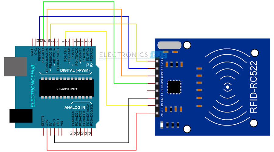
The following image shows all the necessary connection between Arduino UNO and RC522 RFID Module.
Testing RC522 RFID Card Reader
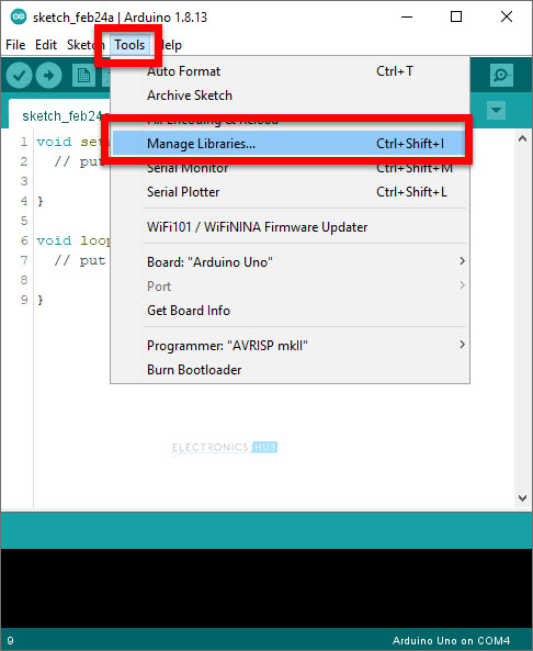
After making all the necessary connections, let us now proceed to test the Arduino RC522 RFID Module Interface. First, open the Arduino IDE and make sure that Arduino UNO is selected as the board. Now, go to Tools -> Manage Libraries. . .
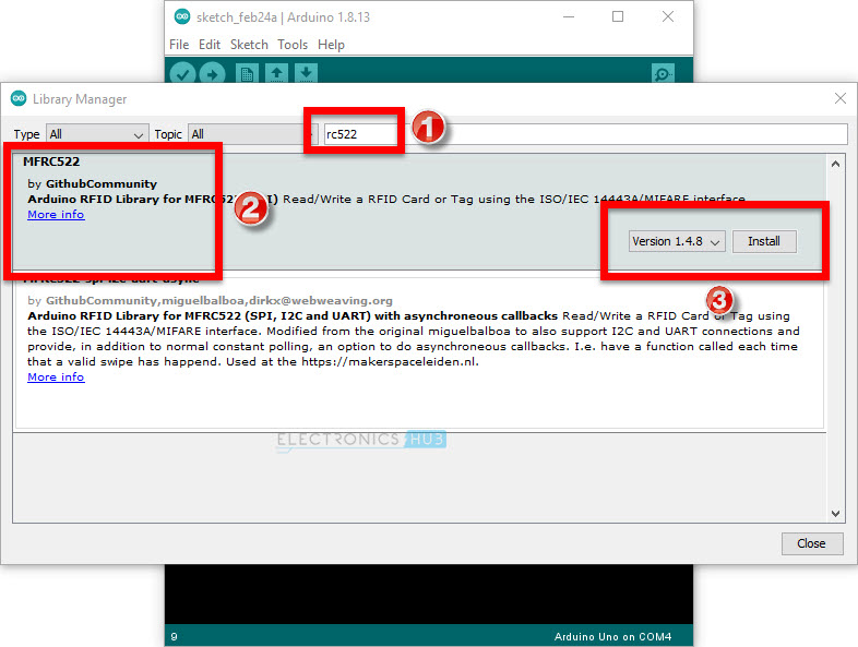
Type “rc522” in the search bar and install the library “MFRC522” by GithubCommunity.
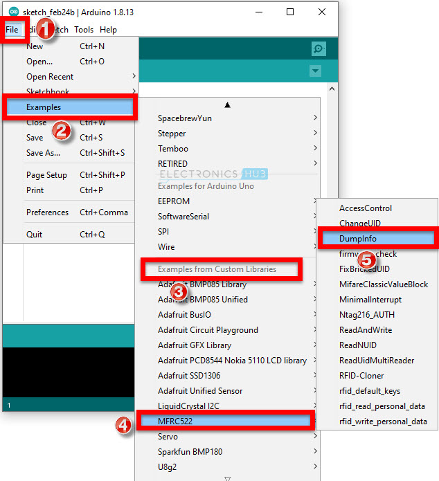
Let us now try an example sketch called “DumpInfo”, which reads data from a PICC (like a card or a key fob) and prints it on the serial monitor. Go to File -> Examples -> MFRC522 -> DumpInfo to open the example sketch.
NOTE: I changed the RST Pin to D7 in Arduino UNO.
Compile and upload the sketch to Arduino and open the serial monitor. The RC522 RFID Reader is waiting for an RFID Tag to be detected. So, take the card, which you got in the kit and place it in the proximity of the RFID Reader (close to the antenna).
You have to hold the card in that position for couple of seconds until all the data is printed. Do not take out the card too soon. You will get an error message “Timeout in communication” if you remove the card early. Once all the information is printed, you can take out the card.
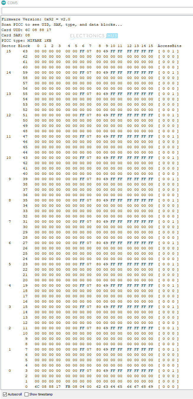
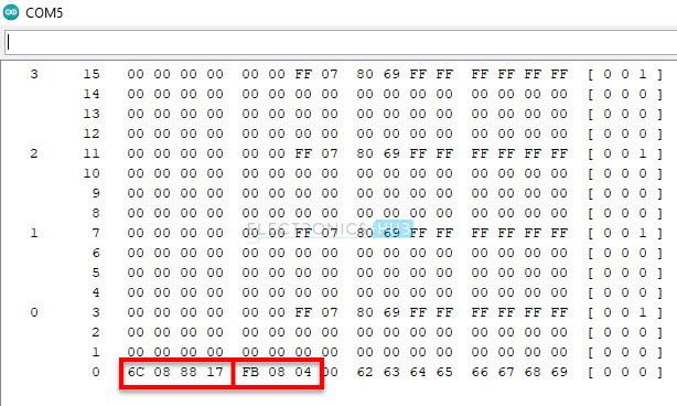
The following is a screen shot of serial monitor for DumpInfo sketch.
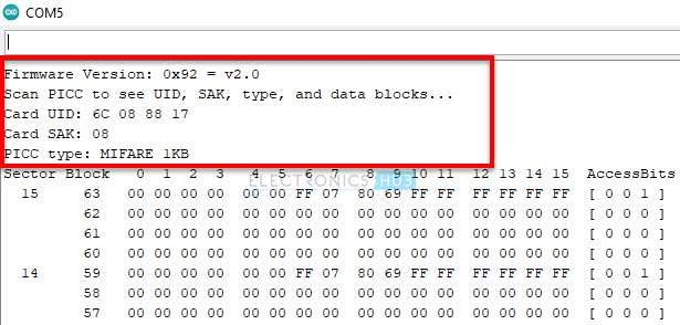
The first few lines are firmware version of PCD (RFID Reader) and details of the PICC (RFID Tag) like the UID, SAK and type of Card.
After this is the main memory dump of the RFID Tag. Let us now analyze it.
Analyzing the Memory Map of MIFARE Classic 1K Card
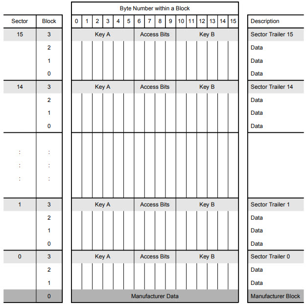
The RFID card and the key fob are of type MIFARE 1K, which means the EEPROM in the PICC i.e., the RFID Card or Key Fob is of 1 KB. This 1KB of memory is organized in to 16 Sectors.
Each sector is again divided into 4 Blocks and each Block contains 16 Bytes of memory. So, the total memory is:
In this, the Block 0 i.e., first block in Sector 0 is reserves for Manufacturer Data. It usually contains a 7 Byte UID (Unique ID) or a 4 Byte NUID (Non-Unique ID).
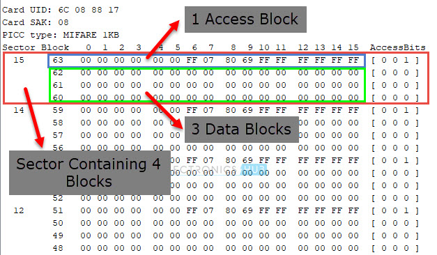
As mentioned earlier, each sector consists of 4 Blocks. In this, the first three blocks are Data Blocks and the fourth block is Sector Trailer. The three data blocks of each sector can be used for storing 16 Bytes of data each.
The last block is each sector is its trailer. It contains two secret keys (Key A and optional Key B) and Access Bits. The Access Bits in the sector trailer determine the access condition (read, write, etc.) for the remining three blocks of the sector.
NOTE: Sector 0 contains only 2 Data Blocks as Block 0 is reserved for manufacturer data and Block 3 is Sector Trailer.
In the next tutorial, I will show you how to write data to PICC i.e., an RFID Tag using RC522 Reader / Writer Module and Arduino. Also, we will make an Access Control project.
Conclusion
A complete beginner’s guide to MFRC522 IC based RC522 RFID Reader Module. You learned about the RC522 Module, how to interface Arduino and RC522 and also how to read the data from an RFID Tag.



2 Responses
Very informative and nicely explained. Thanks
nice ,very informative for beginners,thanks
best regatds
manoj vora