Capacitance Meter, as the name suggests, is a device that is used to measure the Capacitance of a Capacitor. There are many Capacitance Meters available in the market but we have built an Arduino Capacitance Meter in this project.
A Capacitor is an electrical device that stores electric charge and this ability of the capacitor to store the electric charge is known as its Capacitance. With the help of a Capacitance Meter, we can measure the rate of charge storage of the capacitor and based on this, we can get the Capacitance of the Capacitor.
Simple Digital Multimeters (DMMs) cannot measure the capacitance and in order to find the capacitance, you either need to go for an advanced, expensive DMM or find a dedicated Capacitance modules.
The dedicated capacitance meters often come with a wide range of measurements of different parameters like Capacitance, inductance, resistance, hFE of a transistor etc.
In this project, we will try to build a simple Arduino Capacitance Meter for two different ranges of capacitances. One circuit will be used to measure a capacitance in the range of 1 µF to 4700 µF. The other circuit will be used to measure smaller capacitance i.e. in the range of 20 pF to 1000 nF.
Warning: If you want measure the capacitance from an old circuit or board, be careful as a capacitor in working condition may store charge even if the power supply is removed. Discharge the capacitor properly before touching it.
Outline
ToggleCapacitance Meter for Range 1 µF to 4700 µF
Circuit Diagram
Components Required
- Arduino UNO [Buy Here]
- 16 x 2 LCD Display [Buy Here]
- 10 KΩ Potentiometer
- 10 KΩ Resistor (1/4 Watt)
- 220 Ω Resistor (1/4 Watt)
- Breadboard
- Connecting wires
- Power supply
- Capacitor under test
Working Principle
In order to measure the capacitance in the range of 1 µF to 4700 µF, we have to use the above circuit. Before explaining the working of the project, we will first see the principle behind this method of capacitance measurement.
The principle behind this capacitance meter lies in one of the basic property of the capacitor: The Time Constant. Time Constant (denoted by Greek Alphabet Tau – τ) is defined as the time taken to charge a capacitor (C) through a resistor (R) to reach 63.2 % of the maximum supply voltage.
Alternatively, the Time Constant (τ) of a capacitor can also be defined as the time taken by a fully charged capacitor C to discharge to 36.8 % of its maximum voltage through a resistor R.
Smaller capacitors will have less time constant as they take less time to charge. Similarly, larger capacitors will have higher time constants.
Mathematically, Time Constant TC or τ = R x C (τ = RC).
Here, τ or TC is the time constant of Capacitor in seconds (s), C is the Capacitance of the Capacitor in Farads (F) and R is the Resistance of the Resistor in Ohms (Ω).
The following circuit and graph will show you the time constant curve for a Capacitor C, charging to supply voltage V through a Resistor R.
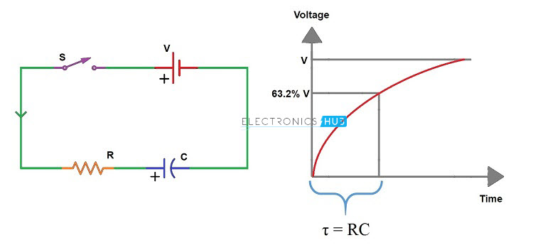 We use the same concept in our Arduino based Capacitance Meter. We will charge an unknown capacitor through a known resistance using Arduino pins and calculate the time it takes to reach 63.2 % of supply voltage (3.1 V approximately). Based on the time, we can calculate the Capacitance from the formula C = τ / R.
We will use a 10 KΩ Resistor to charge the capacitor and a 220 Ω Resistor to discharge it. The charge and discharge pins on Arduino are 8 and 9 respectively. The voltage across the capacitor is measured using the Analog Input pin A0.
Initially, we will discharge the capacitor using pin 9 (by setting it as OUTPUT and LOW) to make sure that the capacitor has no charge. We will then start the timer and charge capacitor using the charge Pin8 (by setting it as OUTPUT and HIGH).
Now, we have to monitor the voltage across the capacitor at the analog pin and once it reaches 63.2% of 5V (approximately 648 from analog pin), we have to stop the timer and calculate the capacitance.
This circuit is suitable for comparatively higher capacitance values as we can clearly measure the time constant. For smaller capacitance values, this circuit might not be suitable.
Code
Capacitance Meter for Range 20 pF to 1000 nF
Circuit Diagram
Components Required
- Arduino UNO
- 16 x 2 LCD Display
- 10 KΩ Potentiometer
- Capacitor under test
- Connecting wires
- Breadboard
- Power supply
Working Principle
For measuring smaller capacitances, we will use a different concept. For this we need to understand a little bit about the internal structure of ATmega328P.
All the I/O ports in ATmega328P Microcontroller have an internal pull – up resistor and an internal capacitor connected between the pin and ground. The following image shows the partial internal circuit of an I/O pin of ATmega328P Microcontroller.
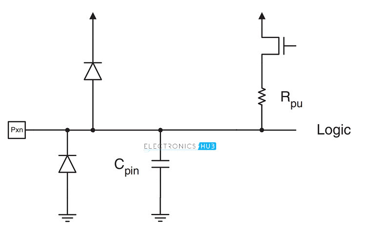 We will be using the internal pull – up resistor and the stray capacitor in this circuit. Ignoring the diodes in the above circuit, the circuit for our project can be redrawn as follows.
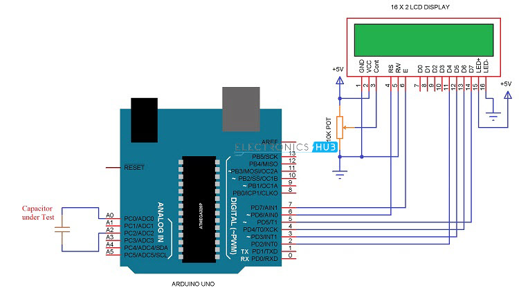
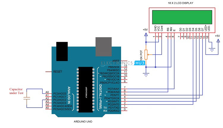 Here, CT is the capacitor under test and CI is the internal capacitor. We need not worry about the internal capacitor and its value can be anywhere between 20 pF to 30 pF. The unknown capacitor is connected between A2 and A0 (Positive lead to A0, in case of polarized capacitor). Here, A2 acts as the charging pin and A0 acts as the discharging pin.
Initially, we will charge the unknown capacitor by setting A2 as HIGH and measure the voltage at A0 from the following formula.
VA0 = (VA2 X CT)/(CT+CI)
But we already know voltage at A0 with the help of analog read function. Hence, using that value in the above equation, we can get the unknown capacitance as follows.
CT = (CI X VA0)/(VA2-VA0 )
Code
Advantages
- It is a simple Arduino based Capacitance Meter with very less hardware requirements.
- The project can be used to measure any capacitance within the range of 20 pF to 4700 µF.
Disadvantages
- Results might not be accurate.
- For accurate results, it is suggested to go for DMMs which can measure capacitance.
Applications
- Capacitance Meter can be used to measure capacitance of unknown capacitors.
- Using Arduino for Capacitance Meter makes it easy to implement the project and with slight modifications, the circuit can be made for a wide range of capacitors.
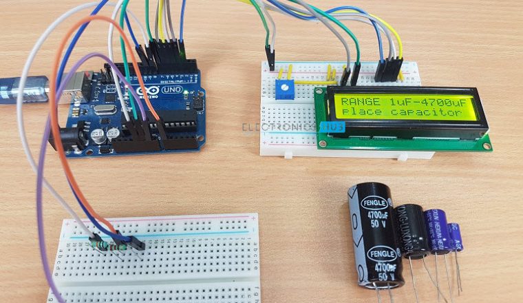
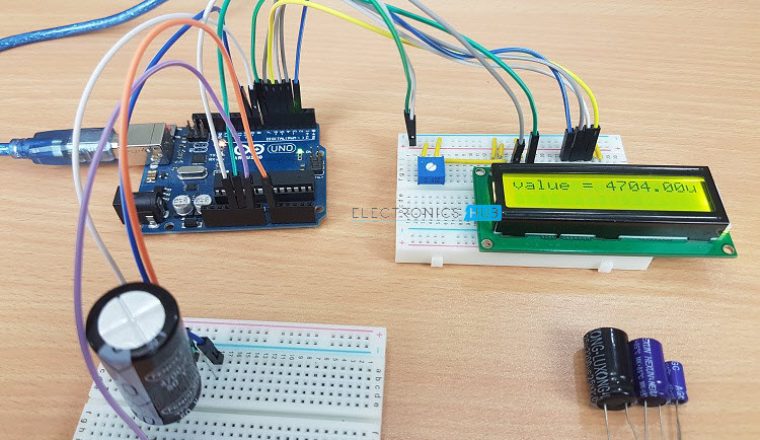
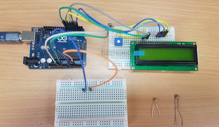
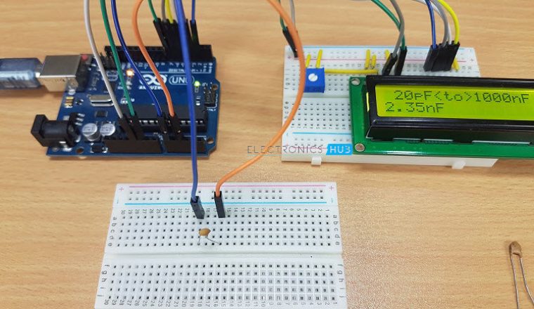
Construction and Output
Recommended read:



4 Responses
Hello Anusha mam……im monika we r looking for ur project I.e. Restaurant menu ordering system.for that we need ur help so can I get urs no.for contact if it needs…..
I thought it was a mistake at first that the discharge pinMode was being set to INPUT;
pinMode(discharge,INPUT);
pinMode(charge,OUTPUT);
But I think it’s so that it’s not pulling the discharge pin high or low while the charge pin is output HIGH and charging the cap.
And then the modes switch later so that the discharge pinMode is OUTPUT and the charge pinMode is INPUT so that it’s not influencing the discharging.
I think at the “Capacitance Meter for Range 20 pF to 1000 nF” you accidently showed the wrong picture for the redrawn circuit.
But nevertheless, great project!
The values are not stable, this is maybe because of analogread() noise in sensor/variable capacitor sensors. So, can you give a solution for it?