While parking the car the driver should be more careful because he cannot see the back of the car while parking or taking reverse, if there is any obstacle and ran over it might be get damage to the car. Our project will help the person in the driving seat and give alarm if there is any obstacle or a wall while parking or while driving in reverse.
Block Diagram of Car Parking Guard:
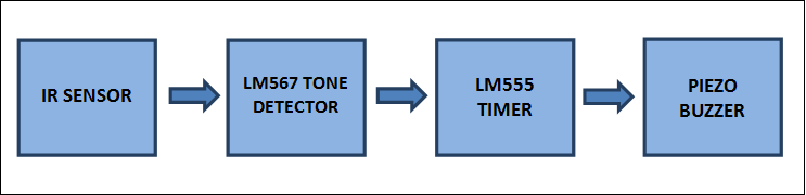
The IR sensor will detect the obstacle with in 100cm, if there is any obstacle it will sense and give information to the tone detector which will enable the LM555 timer to generate a PWM for the buzzer. The LM555 will generate the pulse which helps to buzz the buzzer so driver can understand that there is an obstacle.
Car Parking Guard Main Components:
LM567: is a tone detector which can interpret the frequency generated by the other component and give the output according to the application designed by the engineer. For example if a component is attached to the input of LM567 which can generate a 40 kHz signal , but we to function the following circuit when the component has reached to the 40KHz. At this decision making we will use tone detector. The tone detector is mainly used in touch tone decoders, ultrasonic controls, frequency monitoring and control etc.
LM555: is a timer which can generate a PWM signals in various width and duty cycles. The 555 timer is mainly used to control the other peripherals like motors, detectors, regulators etc.
IR Sensor: the main function of the IR sensor is to produce a beam for certain distance (the distance of the beam is always depends on the IR sensor, different IR sensor have different range of beam distance) if the there is any obstacle in the beam it will conduct and give signal.
Photo Darlington Transistor: the photo darlington transistor will act as a photo detectors. They will conduct to the light or electro magnetic signals. The main function of this transistor is to amplify the input signal of the transistor. But it will work slowly when compared to the other transistors. It is having a maximum frequency of 20 KHz.
Circuit Diagram of Car Parking Guard: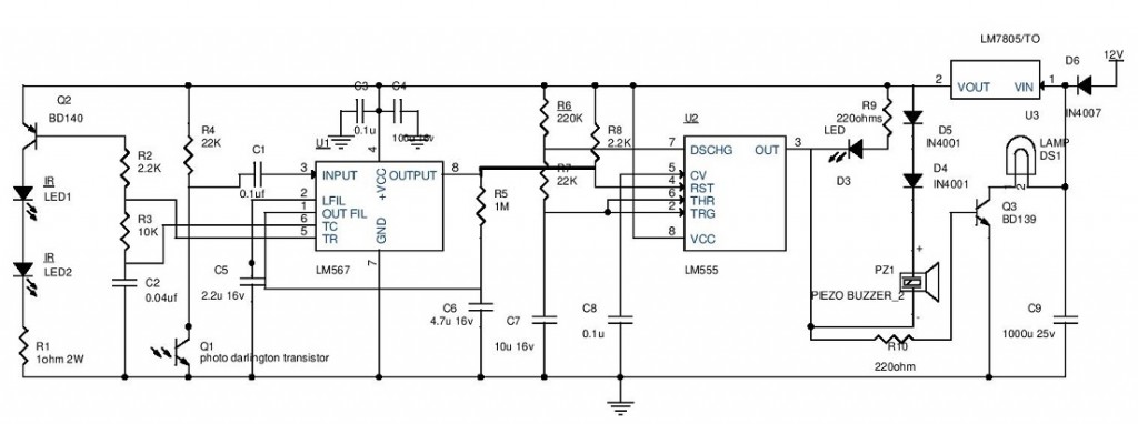 Explanation:
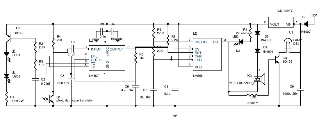
- The reverse indicator light supply is given to the 7805 regulator to give 5v to the rest of the circuit. The diode D6 is used to eliminate the reverse current and wrong supply polarity.
- When the car is driving in reverse the car battery will provide DC supply the reverse light indicator at the back of the car when this supply came to the reverse light indicator the circuit will have the power supply.7805 will regulate the DC voltage to 5V and give to the IR Sensors through the transistor with 20 KHz modulating frequency of the LM567 (TONE DETECTOR) available at Pin5. The resistor R1 will resists the IR senor current. At this point the pin8 of LM567 is high which will enable the LM555 timer operating in astable multivibrator mode. The output of the timer is enabled which can be assured by the LED (blinking) and also buzzer will beeps at determined rate given by the resistors R6, R7 and capacitor C7. The timer output also is given to the lamp through a transistor. The lamp will blink as a warning signal because of the PWM signal generated by the timer, transistor will work as a switch and resistor R10 will limit the current. This condition is maintained until the 20 KHz signal is received by the pin3 of the LM567.
- The above condition is when there is no obstacle in the path of the car while taking reverse. If there is a obstacle the IR beam will radiate back to the IR sensor and the 20KHz modulated signal is given to the pin3 of LM567 through photo Darlington transistor, at this point the pin8 of the LM567 is turned to low and also gets locked to detect the 20Khz signal. By this the LM555 is turned low and disabled by this the led will remain lighting and buzzer makes the continuous sound to alert the driver.
Note: This complete circuitry will be attached to the back bumper and placed at the center. The buzzer and led should be placed on the dash board for visibility of light and hearing purpose for the driver.
Make the connection to the reverse indicator light and the circuit in parallel and beware of the polarity.
Important Post: Water Level Alarm Using 555 Timer

28 Responses
WILL YOU GIVE THE IMAGES OF FINAL PRODUCT AND PROGRAM TOO…….
hi i want some new projects
plz provide me some latest mini project topics with abstract n circuit diagram in electronics.
sure… we are here for you, we will update frequently…
thanks for your comment..
can IR sensor detect glass wall during car riversing
dear sir, i need 10 channel ir based circuits
can u please send me a projects book pdf file coz i’m very keen to learn
Hi! Follow this site regularly. You may get more knowledge on electronics projects and circuit diagrams. We are providing lot of information in near future.
hi,we took this circuit as our mini project.but the problem is we cant implement the same as this circuit.that is we want to modify this circuit.for this we decided to calculate the time taken to transmit and receive of signal by IR sensors.but some people said it is difficult to calculate the time.please reply your suggestion for modifying this circuit.give me the Email ID of Admin if it possible.please reply,we don’t have much time.!!!!
can we fix the camera to detect the objects, in this circuit?
need more electronics final year project for undergraduate students.
thanks alot sir
thank you please send this to my mail id
what about the base terminal of photo darlingtan transistor ,where should it connect?
is it connected or not?
plzz reply as earlier as possible
hi sir i want some new project
please provide some new embedded project
How I can make a car sensor in which only my car enters if some other car will park there the buzzer will ring .plz help me because this model will go to national level.send me your ideas on adilamba14 @gmail.com
WHAT DISTANCE THIS CIRCUIT WII MAINTAIN TO DETECT OBSTACLE
Its depends on your ir led and photo detector range.
I’m going to implement this project. But I’m not sure about the specification of the element ‘Photo Darlington Transistor’. Can you please explain me about the component?
Can i use 9v supply for this project?
and any alternate ic for lm567
can i use 9v battery at suppy
and where to connect other terminal of supply?
Plz answer sir
He sir I want easy project so please give me some idea what I have to make
Will it work…????
And where to connect base of photo darlington transistor???
plz give me the component list and the layout of car parking guard circuit using ir sensor
HI THERE, IM CURRENTLY IN GR9 AND WE HAVE TO DO A TASK ON : IF SOMEONE REVERSES THEIR CAR INTO THE GARAGE , THERE SHOULD BE A DEVICE WARNING HIM NOT TO BUMP INTO THE WALL . NEED IDEAS PLEASE
I am @kash kumar pursuing b- tech in 2nd years from ece. I love making projects, but I don’t know that I have to do it with start at where from, my wish is that my first project should be very memorable
Hi Akash, you have good thought. In my opinion you need to make small circuits and test them. Infact those circuits will a type of project. Once you have the confidence to make some substantial then you can make something meaningful targeting some known problem nearby to you and can share it with your friends and others. I think if you will solve a real problem then it will be really memorable. Wish you the best, good luck!!! Thanks