The need for three-phase supply or service occurs when heavy equipments are present such as large motors (beyond 5 HP motors), because such large equipments need high starting and running currents.
Large buildings, plants and offices have greater power requirements than the power used in domestic installations. Therefore, generally they are often installed with three phase wiring or three-phase supply.
The three-phase power service is generally used for high power rated equipments such as large air conditioners, high rated pump sets, air compressors and high torque motors.
Therefore, it is rarely used for domestic installations, but commonly used in commercial buildings, offices and industrial installations.
Three Phase AC Supply
Three-phase AC power is generated by a three-phase alternator (also called as AC generators) in the power plants.
In the alternator, three stator windings (or say three independent coils) typically separated by some number of degree of rotation and hence the current produced by that coils is also separated by some degrees of rotation, which is typically 120 degrees.
This three phase power from the alternators is further transmitted to the distribution end through transmission lines.
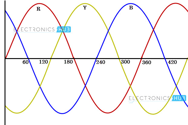
The three phase supply from the distribution line transformer is given to the home or building’s point of service. Most industrial and commercial services consists of three phase systems that are operated typically at 415V phase to phase and 230V phase to neutral.
Three phase system consists of three conductors unlike single conductor in single phase system excluding neutral conductor. In addition to the three phases, additional neutral conductor is required for three-phase four wire system.
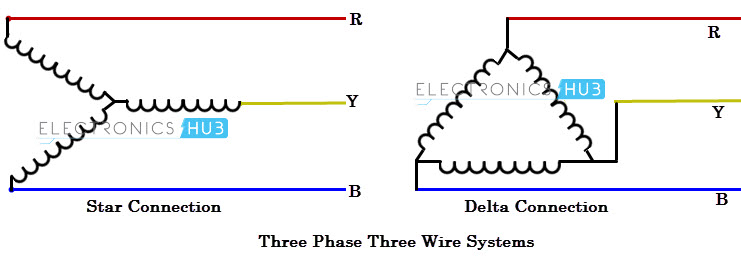
Three-phase systems can be three-phase three wire or three-phase four wire systems. Three-phase 3 line connection consist of three phase conductors and is employed only where there is no requirement for connecting phase to neutral loads.
These connections can be star or delta depending on the secondary of the distribution transformer.
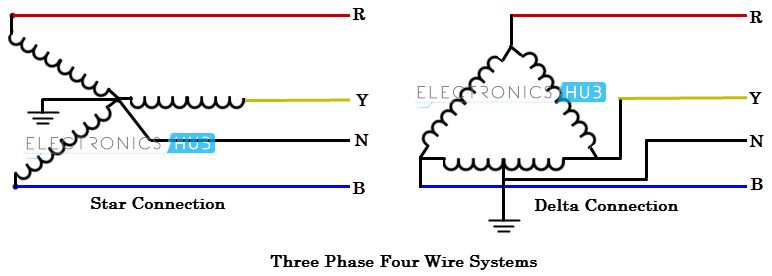
Three-phase 4 wire system is most commonly used connection that consists of three phase conductors and one neutral conductor.
In this three phase wiring, lighting, small-appliance loads and receptacles are often connected between phase and neutral while larger equipments such as air conditioners and electric heaters are connected between two phases (i.e., phase to phase).
Mostly three-phase 4 wire star connection is preferred for connecting both single phase and three phase loads efficiently and in a balanced manner.
This connection allows phase to neutral connection for small loads. Three phase 4 wire delta connection used only where the phase to neutral load is very small compared with three phase load.
Three phase circuits can provide square root of 3 (1.732) times more power compared to single phase power with same current. Thus the three phase system saves electrical installation cost by reducing cable size and size of associated electrical devices.
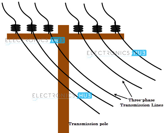
We can easily observe three phase circuits by looking at power line while travelling on roads. Even for a large power transmission system, they are three phase transmission lines unless they are of DC.
Large hotels, restaurants, most factories, office buildings, and grocery stores with heavy refrigeration systems have three phase services.
Three-phase Power Distribution for Industrial Environment
Industries or factories are installed with three phase power in order to connect heavy machineries and equipments. Busbars carries this three phase power and from which individual connections are brought out ,to individual loads , through cables. The figure below shows schematic diagram for industrial three phase wiring.
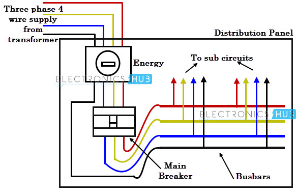
Three phase power from the utilities is connected to the main breaker through three-phase energy meter. The power in the main breaker is then given to various busbars.
This panel is also included with metering arrangement to display parameters like current, voltage, energy and power. The figure below shows the power distribution from main panel to machinery and lighting loads.
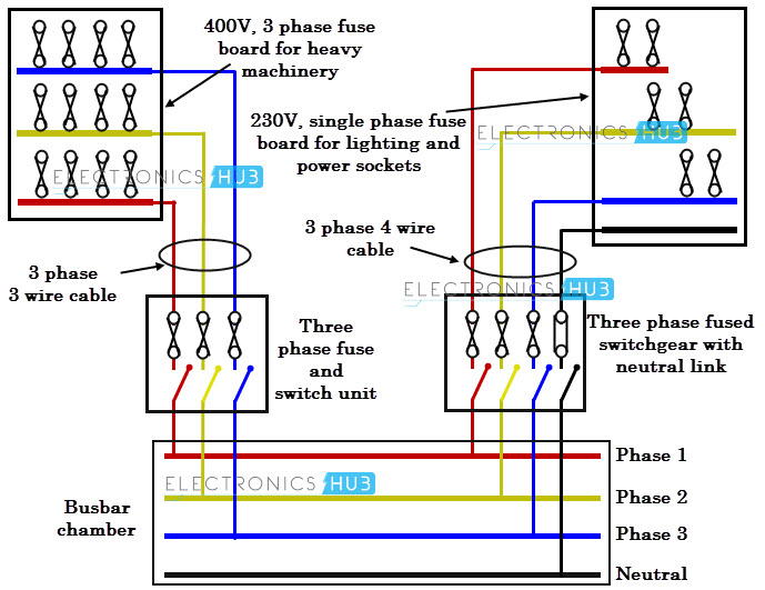
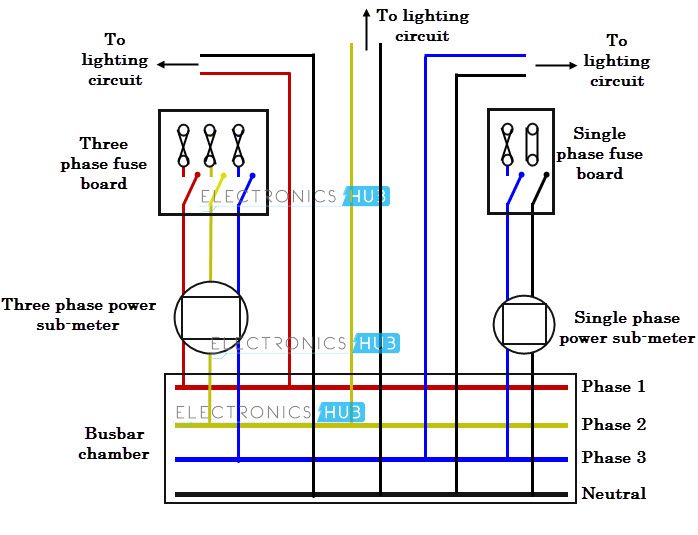
Power from the main distribution board is distributed to heavy machinery equipments as well as to lighting boards with power sockets. The power distributed through single and three phase sub-meters is shown in figure below.
The three phase power distribution to homes or offices is necessary if the load requirement cannot be handled by a single phase supply. The efficient usage of three phase power depends on balancing load distribution on each phase of the three phase supply.
So the single phase loads in the offices or homes must be connected to each phase such that maximum possible load balancing will be achieved.
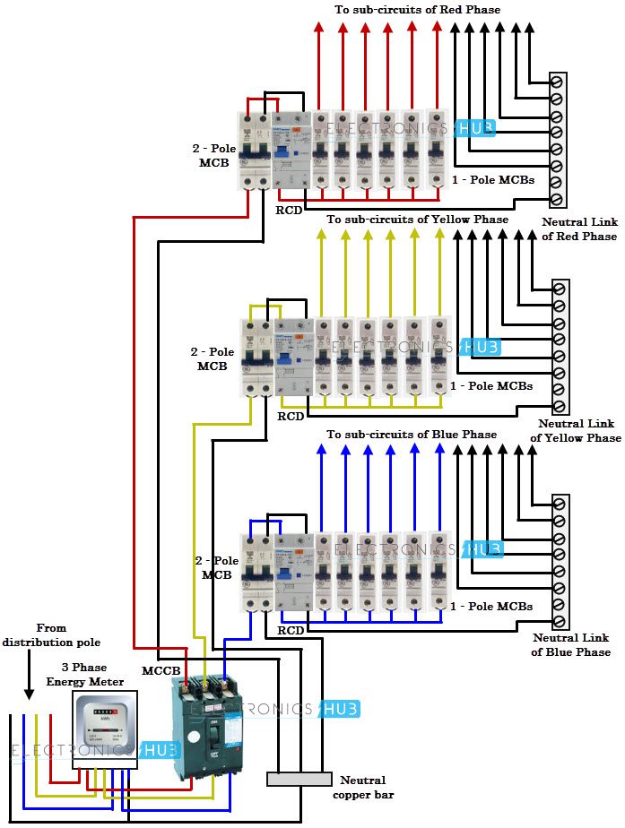
The main components in the three-phase wiring to home or building or office premises are shown in figure below.
In this, the service entrance conductors are connected to a three phase entrance panel. This panel has a three phase main breaker or sometimes it has three separate cartridge fuses.
This three phase breaker consists of three input lugs to energize three vertical busbars. This main breaker has single handle such that all the loads are powered down simultaneously and also in case of electrical faults, it trips or opens all loads simultaneously.
The power from this main panel is connected to the branch circuits. The main panel may consists of single pole or double pole or triple pole breakers for these branch circuits where phase to ground, phase to phase or three phase loads are connected.
In the above figure power from the utility pole is connected to sub-circuits via three phase energy meter, three phase breaker (3-pole 60A), double pole RCD, double pole MCB and single pole MCBs.
Single phase and three phase loads connection to three phase power supply is shown in figure below. We can connect the single phase loads to three phase sub-circuits via switches or MCBs.
But for three phase loads like motors have to be connected to three phase supply via contactor or breaker arrangement.
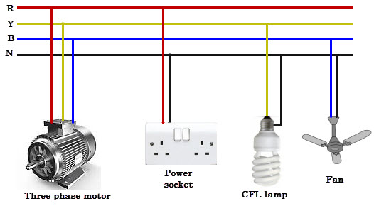
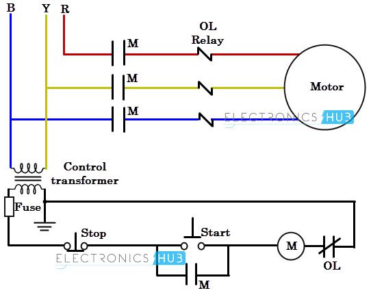
A three pole breaker with an appropriate current rating is used for connecting a three phase motor. Proper care should be taken while connecting three phase wires to the motor because the direction of rotation can be reversed simply by reversing any of the two wires of three phase system.
The wiring diagram for connecting thee phase motor to the supply along with control wiring is shown in figure below. This is a start-stop push button control schematic which includes contactor (M), overload relay, control transformer, and push buttons.
The contactor contains large load contacts that are intend to handle large amount of current. The overload relays protect the motor from overload condition by disconnecting power to the coil of the contactor.
The above mentioned information and diagrams illustrated only for giving basic understanding of three phase power supply distribution to homes and industries.
Instead of concentrating on the values of various equipments, or rating of circuit breakers and other cable sizing, we just gave a brief idea about this topic. Kindly contact us, if you need any further assistance about three phase wiring topic.


12 Responses
respectes sir
‘YOU HAVE GUIDED THE ORDINARY PERSON BY A NICE WAY.
THANKS
So good I am going to do fitting of three fase actually in a collage lightning, heating and matching but I don’t knew what I can do
I want to do wireing 3fase in a collage and three fase in every room every lamp and now question is how can I do this type of wireing reply plz plz
Thanks you so mush.
perfect
Sir can we use 35mm cable for connection from EB post to residence which is 600 Meter distance instead of EB post.
Sorry I did not see Phase Selectors or Phase Selectors Wiring which is critical to me.
thanks you
very good ILLUSTRATED and best explanation
good, I do my own and sometimes i am confused
Dear sir,
Hi, thank you for your good instructions and drawings, I have a problem as follows:
there is a 3 phase electrical meter and I want to ad a 1 phase to the system, say to decrease the energy consumption, could I connect one of the incoming phases to the 1 phase meter and leave the three phase meter with two phase connected, so the out going lines are as follows:
2 wires from the three phase meter
1 wire from the 1 phase meter
all neutrals are connected to each other i.e. common neutral
in fact this arrangement made from the previous owner of my house, and probably he meant to decrease electrical consumption, and system worked.
would you please guide me about the wisdom of such connection
Regards
Good. Thanks
Thanks sir