Display Devices are very useful in many embedded systems irrespective of their type or size. Character LCD (the 16×2 LCD) is a simple display unit that can output various alphanumeric characters and some special symbols. A Graphical LCD (128×64 LCD) on the other hand, can display bitmap images (and characters of different font size). Not all projects/applications need such complex display unit as some systems will do just fine with a 7 Segment Display. In this guide, we will take a closer look at some interesting points about a 7-Segment Display and also check out the 7 Segment Display Pinout.
Outline
ToggleAn Overview of 7 Segment Display
A 7 Segment Display is one of the simplest types of display devices that can display numbers from 0 through 9 (you can also display characters from ‘A’ through ‘F’). The name ‘7 Segment Display’ means that it has 7 LEDs in the form of hexagonal bars that are arranged in the form of ‘8’.
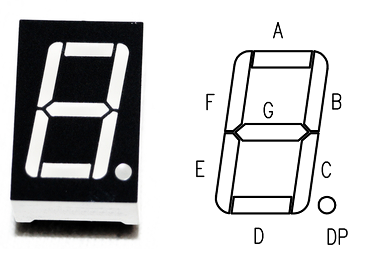
Each LED is known as a ‘Segment’ with names A, B, C, D, E, F and G. Most 7 Segment Display have an additional segment in the form of a dot. It is technically an 8 Segment Display with 7 Segments responsible for displaying the main numerical data and one dot segment.
You can see in the following image the side-by-side representation of a typical 7 Segment Display and it Segment names.
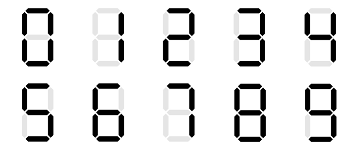
To display a particular number, you have to turn ON or OFF a group of Segments. For example, to display the number ‘0’, all the segments must be ON except the segment ‘G’. You can see how numbers from ‘0’ through ‘9’ will look on a typical 7 Segment Display in the following image.
Types of 7 Segment Displays
Till now, we have spoken only about the output of the 7 Segment Display. But what about its internal circuitry and components? As each segment in a 7 Segment Display is nothing but an LED, the internal circuit and components are nothing but a bunch of LEDs connected in a special pattern (an additional LED for the dot).
Based on the internal connection of the LEDs, we have two basic types of 7 Segment Displays. They are Common Anode and Common Cathode.
In a Common Anode type 7 Segment Display, the anodes of all the 8 LEDs are connected together and made common for the entire display unit. As a result, we have just 9 pins/connections to control the entire 7 Segment Display unit (8 Cathode pins of 8 LEDs and one common Anode pin).
The following image shows the internal connection of a Common Anode type 7 Segment Display.
Coming to the Common Cathode type 7 Segment Display, you guessed it right, the connection is just the opposite. All the cathode terminals of the 8 LEDs are connected together and made common.
There is one important thing about common anode and common cathode type 7 Segment Displays that you need to remember. In case of Common Anode 7 Segment Display, we connect the common anode pin to VCC (i.e., positive of the power supply, usually +5V) all the time. To turn ON a particular segment, we make the corresponding cathode pin LOW.
In case of Common Cathode 7 Segment Display, we connect the common cathode pin to GND (i.e., negative of the power supply) all the time and make a particular anode pin HIGH to turn ON the corresponding segment.
We will see more about this when we see the 7 Segment Display Pinout for both common anode and common cathode types.
7 Segment Display Pinout
Let us now see the 7 Segment Display Pinout for both Common Anode as well as Common Cathode types. The difference is actually very small, which you will see.
Common Anode
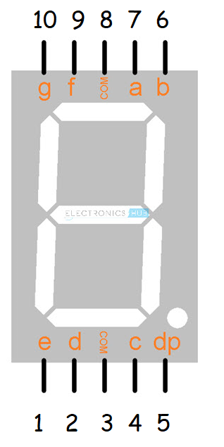
The following image shows the Common Anode 7 Segment Display Pinout. Note that, the Pins 3 and 8, which are named COM are connected internally and, in this case, they are the common anode Pins (+5V).
| Pin | Connection |
| 1 | Cathode E |
| 2 | Cathode D |
| 3 | Common Anode |
| 4 | Cathode C |
| 5 | Cathode DP |
| 6 | Cathode B |
| 7 | Cathode A |
| 8 | Common Anode |
| 9 | Cathode F |
| 10 | Cathode G |
To display digits ‘0’ to ‘9’ on this common anode display, we have to follow the following digital logic. Here, ‘1’ indicates logic HIGH (+5V) and ‘0’ indicates logic LOW (0V, GND).
| Number to Display | Segment A (Pin 7) | Segment B (Pin 6) | Segment C (Pin 4) | Segment D (Pin 2) | Segment E (Pin 1) | Segment F (Pin 9) | Segment G (Pin 10) |
| 0 | 0 | 0 | 0 | 0 | 0 | 0 | 1 |
| 1 | 1 | 0 | 0 | 1 | 1 | 1 | 1 |
| 2 | 0 | 0 | 1 | 0 | 0 | 1 | 0 |
| 3 | 0 | 0 | 0 | 0 | 1 | 1 | 0 |
| 4 | 1 | 0 | 0 | 1 | 1 | 0 | 0 |
| 5 | 0 | 1 | 0 | 0 | 1 | 0 | 0 |
| 6 | 0 | 1 | 0 | 0 | 0 | 0 | 0 |
| 7 | 0 | 0 | 0 | 1 | 1 | 1 | 1 |
| 8 | 0 | 0 | 0 | 0 | 0 | 0 | 0 |
| 9 | 0 | 0 | 0 | 0 | 1 | 0 | 0 |
Note that we did not mention the COM pin i.e., the common anode pin in the above table as we need to connect to +5V all the time.
Common Cathode
Now the pinout of common cathode type. The following image shows the Common Cathode 7 Segment Display Pinout. It is exactly same as the pinout of the common anode type but the difference lies internally.
| Pin | Connection |
| 1 | Cathode E |
| 2 | Cathode D |
| 3 | Common Cathode |
| 4 | Cathode C |
| 5 | Cathode DP |
| 6 | Cathode B |
| 7 | Cathode A |
| 8 | Common Cathode |
| 9 | Cathode F |
| 10 | Cathode G |
The COM pins (Pins 3 and 8) in case of Common Cathode 7 Segment Display is actually the common cathode pin instead of the anode pin (in case of common anode type).
Now, to drive a common cathode the logic is simply the reverse of the common anode type what we saw earlier. To make things easier, use the following table as a reference.
| Number to Display | Segment A (Pin 7) | Segment B (Pin 6) | Segment C (Pin 4) | Segment D (Pin 2) | Segment E (Pin 1) | Segment F (Pin 9) | Segment G (Pin 10) |
| 0 | 1 | 1 | 1 | 1 | 1 | 1 | 0 |
| 1 | 0 | 1 | 1 | 0 | 0 | 0 | 0 |
| 2 | 1 | 1 | 0 | 1 | 1 | 0 | 1 |
| 3 | 1 | 1 | 1 | 1 | 0 | 0 | 1 |
| 4 | 0 | 1 | 1 | 0 | 0 | 1 | 1 |
| 5 | 1 | 0 | 1 | 1 | 0 | 1 | 1 |
| 6 | 1 | 0 | 1 | 1 | 1 | 1 | 1 |
| 7 | 1 | 1 | 1 | 0 | 0 | 0 | 0 |
| 8 | 1 | 1 | 1 | 1 | 1 | 1 | 1 |
| 9 | 1 | 1 | 1 | 1 | 0 | 1 | 1 |
4 Digit 7 Segment Display Pinout
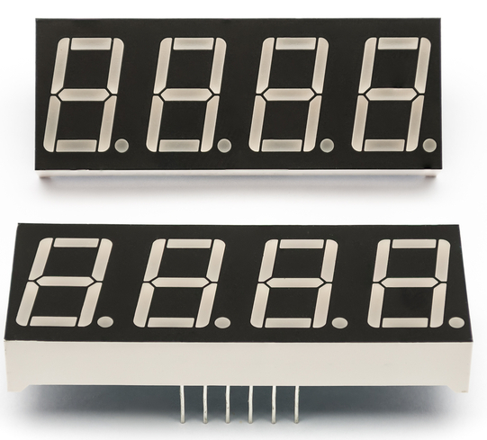
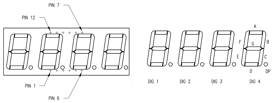
A special type of 7 Segment Display is the 4-Digit 7-Segment Display. It consists of four 7 Segment Displays in a single package. This is very useful in designing clocks and timers.
Like single 7 Segment Displays, even 4-Digit ones are available as both common anode and common cathode types. The following image shows the typical 4 Digit 7 Segment Display Pinout.
Note that it is essentially 4 individual 7 Segment Display with respective segments and a dedicated ‘Common’ pin (either a common anode or common cathode).
| Pin | Connection |
| 1 | Cathode E |
| 2 | Cathode D |
| 3 | Common DP |
| 4 | Cathode C |
| 5 | Cathode G |
| 6 | Digit 4 Common (Anode or Cathode) |
| 7 | Cathode B |
| 8 | Digit 3 Common (Anode or Cathode) |
| 9 | Digit 2 Common (Anode or Cathode) |
| 10 | Cathode F |
| 11 | Cathode A |
| 12 | Digit 1 Common (Anode or Cathode) |
Conclusion
7 Segment Displays are very simple devices that can display digits from 0 – 9 and even characters from A – F. If your project/application involves only displaying number (Decimal or Hexadecimal), then a 7 Segment Display is the cheapest option available. In this guide, we saw some basics of 7 Segment Display, their internal architecture/circuitry and also the 7 Segment Display Pinout for Common Anode as well as Common Cathode types. Finally, we also saw the 4 Digit 7 Segment Display Pinout.

