There are many different types of resistors available. In order to identify or calculate the resistance value of a resistor, it is important to have a marking system. Resistor Color Code is one way to represent the value of the resistance along with the tolerance.
Resistor color code is used to indicate the value of resistance. The standards for color coding registers are defined in international standards IEC 60062. This standard describes color coding for axially leaded resistors and numeric code for SMD resistors.
Outline
ToggleResistor Color Codes
There are several bands to specify the value of resistance. They even specify tolerance, reliability and failure rate. The number of bands vary from three to six. In case of 3 band code, the first two indicate the value of resistance and the third band acts as multiplier.
Three Band Resistor Color Code
- The three band color code is very rarely used.
- The first band from the left indicates the first significant figure of the resistance.
- The second band indicates the second significant number.
- The third band indicates the multiplier.
- The tolerance for three band resistors is generally 20%.
- The color code table corresponding to three band resistors is shown below.
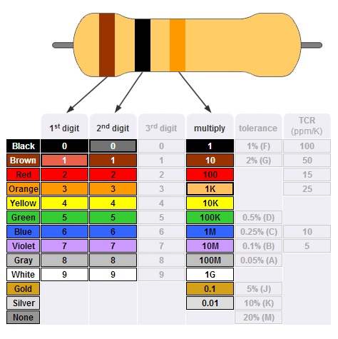
For example if the colors on the resistor are in the order of Yellow, Violet and Red from left, then the resistance can be calculated as
47× 102± 20 %. This is 4.7 KΩ± 20%.
This means the resistance value lies in the region of 3760Ω to 5640Ω.
Four Band Resistor Color Code
- Four band color code is the most common representation in resistors.
- The first two bands from the left are used to indicate the first and second significant digits of resistance.
- The third band is used to indicate the multiplier.
- The fourth band is used to indicate tolerance.
- There is a significant gap between third and fourth bands. This gap helps in resolving the reading direction. The color code table for four band resistors is as shown below.
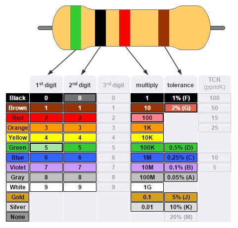
For example, if the colors on a four band resistor are in the order Green, Black, Red and Yellow then the value of resistance is calculated as 50 * 104± 2 % = 500KΩ± 2%.
Five Band ResistorColor Code
High precision resistors have an extra band which is used to indicate the third significant value of the resistance. The rest of the bands indicate the same things as four band color code.
- The first three bands are used to indicate the first three significant values of resistance.
- Fourth and fifth bands are used to indicate multiplier and tolerance respectively.
- There is an exception when the fourth band is either Gold or Silver. In this case, the first two bands indicate the two significant digits of resistance.
- Third band is used to indicate multiplier, fourth band is used for tolerance and fifth band is used to indicate the temperature coefficient with units of ppm/K. The color code table for five band resistors is shown below.
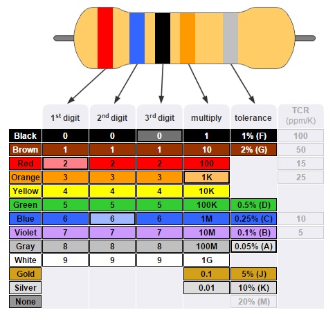
For example, if colors on a five band resistor are in the order Red, Blue, Black, Orange and Gray then the value of resistance is calculated as 260×103± 0.05 = 260 KΩ ± 0.05%.
Six Band ResistorColor Code
- In case of high precision resistors, there is an extra band to indicate the temperature coefficient.
- The rest of the bands are same as five band resistors.
- The most common color used for sixth band is black which represents 100ppm/K.
- This indicates that for a change of 100C in temperature, there can be a change of 0.1% in the value of resistance.
- Generally the sixth band represents temperature coefficient. But in some cases it may represent reliability and failure rate.
The color code table for six band resistors is shown below
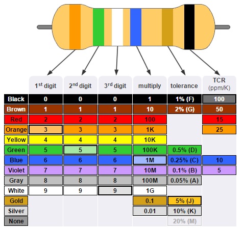
For example if the colors on a six band resistor are in the order Orange, Green, White, Blue, Gold and Black then the resistance is calculated as 359 ×106± 5% 100 ppm/K = 359MΩ± 5% 100 ppm/K.
Tolerance Letter Coding for Resistors
The letter code for tolerance is shown below
- B = 0.1%
- C = 0.25 %
- D = 0.5 %
- F = 1 %
- G = 2 %
- J = 5 %
- K = 10 %
- M = 20 %
K and M should not be confused with kilo and mega Ohms.
SMD Resistor Code
There are three types of coding systems used to mark SMD Resistors. They are
- Three digit coding
- Four digit coding
- E96 coding
Three Digit Code
In three digit coding, the first two numbers indicate the significant value of the resistance and the third number indicates the multiplier like 10 in case the digit is 1, 100 in case the digit is 2 or 1000 in case the digit is 3 and so on.
A three digit coded SMD resistor is shown below

Some examples of three digit codes are
450 = 45 * 100 = 45 Ω
221 = 22 * 101 = 220 Ω
105 = 10 * 105 = 1 MΩ
If the resistance is less than 10Ω then the letter R is used to indicate the position of the decimal point. For example
3R3 = 3.3Ω
47R = 47 Ω
Four Digit Code
For more precision resistors, a four digit code is marked on them. The calculation is similar to three digit code. The first three numbers indicate the significant value of the resistance and the fourth number indicates the multiplier.
A four digit coded SMD resistor is shown below

Some examples under this system are
4700 = 470 * 100 = 470 Ω
1001 = 100 * 101 = 1 KΩ
7992 = 799 * 102 = 79.9 KΩ
For resistors less than 100 Ω, R is used to indicate the position of the decimal point.
For example,
15R0 = 15.0 Ω
E series
Electronic Industries Association (EIA) specified a standard preferred value system for resistors and is named as E series. IEC 60063 is an international standard which defines the preferred number series in resistors (and also for capacitors, inductors and Zener Diodes). The coding is based on the tolerance values and different E series available are
- E3 50% tolerance
- E6 20% tolerance
- E12 10% tolerance
- E24 5% tolerance
- E48 2% tolerance
- E96 1% tolerance
- E192 0.5, 0.25, 0.1% and higher tolerances
- E3 coding is no longer in use and E6 coding is very rarely used.
- The E96 coding system is used for high precision resistors with a tolerance of 1%.
There is a separate coding system in EIA E96 marking system. This system uses three figures for marking. The first two are numerals which indicate the three significant digits of the value of resistance. The third figure is a letter used to indicate the multiplier.
The EIA E96 markings on an SMD resistor is

The EIA 96 code scheme for multipliers is shown below
The EIA 96 code scheme for significant values of resistance is shown below
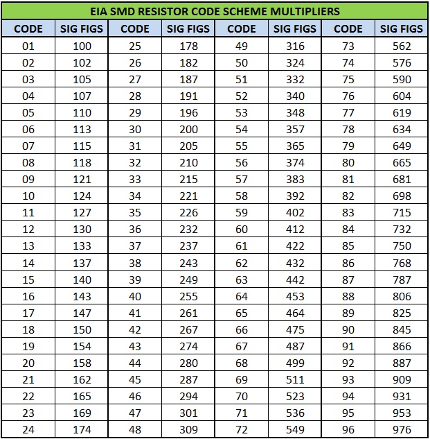
Some examples of EIA 96 coding system are
92Z = 887 × 0.001 = 0.887 Ω
38C = 243 × 100 = 24.3 KΩ
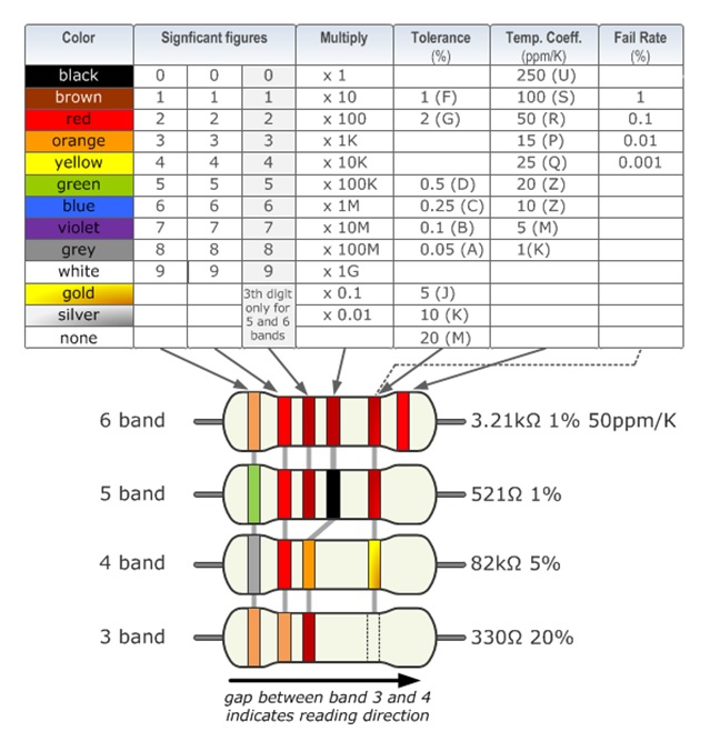
Color Coding Table
The complete color coding table is shown below


2 Responses
Thank you very much for your website
So Very interesting informative & educative .we
ebsite , Thanks a lot,