Source transformation methods are used for circuit simplification to modify the complex circuits by transforming independent current sources into independent voltage sources and vice-versa. To analyse the circuits we can apply a simple voltage and current divider techniques by using these transformations. This source transformation method can also be used to convert a circuit from Thevinin’s equivalent into Norton’s equivalent. Let us know these source transformation methods in brief.
Outline
ToggleSource Transformation Methods
Practical Voltage Source
An ideal voltage source means a device that offer a terminal voltage which doesn’t depend on the current flow through it. But such ideal sources never exist practically. Suppose a battery would produce 12V when no load is connected or no current flows through it, then the battery produce a less voltage than 12V when a load current flows through it. These sources are called as practical voltage sources. However, as long as small power or currents drawn from the load, these practical sources represent the ideal voltage sources.
V-I characteristics of practical voltage source
Therefore, the real model of device (practical voltage source) is obtained by an ideal voltage source with a series resistor. This series resistor resembles the voltage drop in the device when the current flows through it. The series resistor is called as the internal resistance of the voltage source. This does not mean that we can find such arrangement inside every practical source device but merely represents the reduction in terminal voltage on an account for an increase of load current flow.
Practical voltage source with internal resistance
Practical Current Source
Similar to an ideal voltage source, an ideal current source also never exists as there is no device or source that delivers a constant current independent of connected load resistance or the voltage across the load terminals. However, if the load voltage is small, load current in practical current source and current from ideal current source are equal. Therefore, a real model or practical current source is obtained from an ideal current source in parallel with resistance (or internal resistance). This resembles , the current changes in a practical current source with change in voltage of the load (or change in resistance of the load).
Concept of Source Transformations
Consider both practical voltage and current sources with load resistance of RL. Let us see how the circuit behaves for resistance change at the load.
- If the load resistance, RL = 0 in practical voltage source circuit, then the load acts as a short circuit and hence the short circuit current flows through the load. So the VL is zero (VL = IL * RL) and the IL would be
IL = Vs/Rs
- Similarly for RL=0 in practical current source circuit, load also behaves as short circuit as it prefers the current flow through non-resistance path. This load current is equal to the source current Is which is equal to the value of Vs/Rs in practical voltage source circuit.
Therefore, Is = Vs/Rs when RL = 0…………(1)
- If the load resistance RL is infinity, both circuits behaves as an open circuit. Therefore load current is zero in both circuits. And the voltage drop across the resistance Rint in practical current source circuit is Is*Rint
Vint = Is * Rint
- And the voltage across the Rs in a practical voltage source circuit is equal to the Vs which is equal to the Is* Rint of the practical current source circuit.
Vs = Is * Rint when RL is infinity ………………(2)
Hence from equations 1 and 2, we get
Vs = Rs * Is
Vs = Rint * Is
By observing above two equations, if the internal resistance of the two sources is same then the two sources are electrically equivalent. These two sources are equivalent , they can produce the same values of IL and VL when connected to same load resistance. Hence, these equivalent sources can produce identical values of short circuited current and open circuit voltage when zero load resistance and infinity resistances respectively. Therefore, by interchanging the internal resistors we can transform their properties from current source to a voltage source and vice-versa.
Conversion of Voltage Source to Current Source
From the above discussion a voltage source can be converted or transformed into a current source by interchanging a series resistor to parallel as shown in figure.
Steps:
- Find the internal resistance of the voltage source and keep this resistor in parallel with a current source.
- Determine the current flow provided by current source by applying ohms law.
In the above figure, a voltage source with a resistance Rs is transformed into an equivalent current source with a parallel resistor Rs. And this current value is obtained by applying the simple ohms law as
Is = Vs/Rs.
Example:
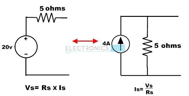
Consider the below voltage source circuit with a voltage of 20 V and a internal resistance of 5 ohms. This circuit is transformed into the current source by placing a resistor of the same value with a current source. This current source value can be determined by,
Is = Vs/Rs
= 20/ 5
= 4 amps
The equivalent current source with a current of 4A and parallel resistor of 5 ohms is shown below.
Conversion of Current Source to Voltage Source
The current source transformed into a voltage source by interchanging parallel resistor in series. Let us see how it could work.
Steps:
- Find the parallel resistance of the constant current source and place in series with a voltage source.
- Determine the open circuit voltage value of the voltage source by applying ohms law.
In the above figure, a current source is converted into a voltage source by placing resistance Rs in series with a voltage source and the value of the voltage source is calculated as,
Vs = Is *Rs
Example:
Consider the below example for current source transformation, where current source is of 10A with a parallel resistance of 3 ohms. To calculate the value of voltage in voltage source apply the simple ohms law, then,
Vs = Is * Rs
Vs = 10 * 3
= 30 Volts.
Therefore the equivalent voltage source of this transformation consists a voltage source 30 V with a series resistance 3 ohms.
Example of Source Transformations
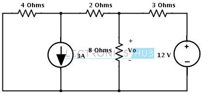
- Consider the below example where we have to find the voltage Vo by applying the source transformation. This circuit consists of both current and voltage sources. Let us see how we can apply source transformation to simplify the circuit below.
- In the circuit there are two areas where we can apply the source transformation since current source has a parallel resistor and voltage source has a series resistor as shown in figure. So these configurations are necessary requirements to apply the source transformation.
- First, consider the current source with a parallel resistance of 4 ohms. This current source can be transformed into a voltage source by 4 ohms series with a voltage source and voltage source value is determined as
Vs = Is * R
= 3* 4
= 12 Volts
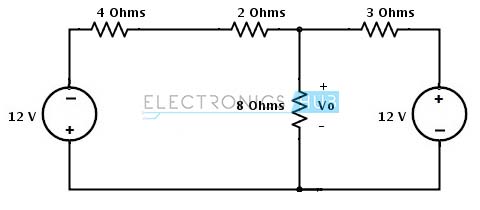
Consider the direction of the current as it downwards so the voltage terminals in voltage source are also changes as shown in figure.
- Place the above voltage source with a series resistance in the circuit, then we get below figure.
- Resistors 4 ohms and 2 ohms are in series , hence the total series resistance will be 6 ohms as shown below.
- Again the voltage source of 12V with series resistor 6 ohms can be transformed into a current source. Therefore consider to transform it.
- This 12V voltage source with 6 ohm resistor combination can be converted into the current source by placing 6 ohms resistor in parallel with a current source. And the value of current in current source can be determined as
Is = Vs/R
= 12/6
= 2Amps
The direction of current flow is represented in below figure.
- Insert the above current source in the main circuit, then we get
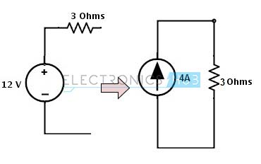
- On the right hand side, there is a voltage source with a 3 ohms resistor so this can be transformed into a current source by placing a 3 ohm resistor in parallel with a current source and this current source value is calculated as
Is = Vs/Rs
= 12/ 3
= 4 Amps
The direction of current in current source is shown in figure.
- Insert the above current source in simplified circuit, then we get a final circuit as
From the above simplified circuit the current sources are appeared to be opposite to each other. The node current through the circuit will be
Is = I1 – I2
= 4-2
= 2 amps
By applying the divider rule, the current through the resistor 8 ohms is
Io = Is * (1/Ro/ ((1/Ro) + (1/R1) + (1/R2))
= 2 * (1/8/((1/8) + (1/6) + (1/3) )
= 0.4 Amps
Therefore, the voltage across the resistor 8 ohms is
Vo = Io * Ro
= 0.4 * 8
= 3.2 Volts


One Response
Interesting… But I arrive at the correct answer a different way..
After getting my three parallel resistors I take them 6inv+3inv+8inv then invert this. This resistance I multiply by the current of 2. I do not get the current divider rule you list.