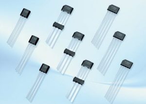
The most commonly used and widespread method of detecting the magnetic field is the Hall-effect method among the various sensing technologies. Based on the Hall-effect, there are numerous Hall-effect sensors or transducers found in a wide variety of applications that are most commonly used for sensing proximity, speed, current and position.
This is because it is possible to build or construct Hall-effect sensors on integrated circuits (Ic’s) with ancillary signal processing circuitry on the same silicon die.
Due to advantages like the small size, ruggedness, ease of use and cost integrated Hall-effect sensors are preferred for many magnetic measurement applications.
Some of the application areas where these Hall-effect transducers are used are; in industrial control as encoders, speed sensors and end of travel sensors, in computers as disk drive index sensors and commutation for brushless fans, in automobiles as antilock braking system (ABS) and ignition timing, in consumer devices as exercise equipment, and so on.
Outline
ToggleTheory of Hall-Effect
The Hall-effect is discovered experimentally by Edwin Hall in 1879 at John Hopkins University. With the instruments available at that time, the voltages obtained from the materials were extremely low (in the order of micro volts) from the subtle nature of the experiment.
And hence no use with Hall-effect, outside of the laboratory was possible till the development of suitable materials. The development of semiconductor materials yielded to the fabrication of high quality transducers for the practical applications of the Hall-effect.
The Hall-effect is the generation of voltage across the opposite edges of current carrying conductor which is placed in a magnetic field.
When an electric current passes through a conductor placed in a magnetic field, a potential difference is developed across the conductor in a direction perpendicular to both magnetic field and the current and its magnitude is proportional to the current and magnetic field.
This is known as Hall-effect and it is basis for many magnetic field measuring instruments and devices.
Consider the simple setup to illustrate the Hall-effect shown below. A conducting material or plate is supplied by a battery such that a current I flows through it. A pair of probes of a voltmeter is connected to the sides of the plates such that measured voltage is zero in the absence of magnetic field.
When a magnetic field is applied to the plate such that it is right angles to the current flow, then a small voltage appears for the current distribution in the conductor. This force acts on the current and crowds the current to the one side of the wire or conductor which resulting a potential difference across the conductor.
If the polarity of the magnetic field is reversed, then the induced voltage also reversed across the plate. This phenomenon is the Hall-effect.
The Hall-effect is based on the interaction between external magnetic field and the moving charge carriers. A side force acting on moving electrons though a magnetic field is given as
F = qvB
Where B is the magnetic flux density, v is the speed of the electrons and q is an electron charge. Consider the above figure in which magnetic field deflects the movement of the charges. A flat conductive strip is placed in a magnetic field and the additional contacts of the strip on left and right sides are connected to the voltmeter.
The lower and upper terminals of the strip are connected to electric supply source. Due to the presence of magnetic flux, moving electrons are shifted towards the right side of the strip by the deflecting force. This results more negative at the right side than left and hence exists a potential difference.
This voltage is called as a Hall voltage whose magnitude and direction depends on both magnitude and direction of electric current and magnetic field. The Hall voltage is given as
VH = HIB sinα
Where h is the coefficient of overall sensitivity, which depends on the plate material, temperature, and its geometry, α is the angle between the magnetic field vector and Hall plate and I is the current density.
The overall sensitivity depends on the Hall coefficient, which is the transverse electric potential gradient per unit current density per unit magnetic field intensity. Thus, the Hall-coefficient is given as
H = 1/ Ncq
Where c is the speed of the light, N is the number of electrons per unit volume.
Hall-Effect Sensors
Most of the sensors use the Hall-effect to sense the presence of magnetic fields , such sensors are called as Hall-effect sensors. The basic element of a magnetic sensor is the Hall-element. These sensors are usually packed in a four-terminal housing in which two terminals are control terminal and other two are differential output terminals.
The control current is applied at the control terminals whereas the output is observed at the differential output terminals. A basic Hall-effect sensor converts the magnetic field to electrical signal.
A magnetic system converts the physical quantities such as position, speed, current, temperature, etc to a magnetic field which in turn can be sensed by Hall-effect sensors.
Hall-effect sensors are fabricated from silicon material and majorly categorized into two types, namely basic sensors and integrated sensors. Hall-coefficient and current density of the active element are the two important parameters to be considered while fabricating the Hall-effect sensors to produce a high output voltage.
Thus, a high Hall-coefficient and low resistance are the two important requirements of the Hall element. Some of the materials used for the fabrication of elements in these sensors include InSb, Ge, InAs and GaAs.
Hall-Effect Integrated Circuit (IC) Sensors
The integrated technology is combined with Hall-effect principle to produce the Hall-effect IC switches. As compared with optoelectronic or inductive sensors, the Hall-effect ICs are more effective, less costly and more efficient.
This kind of sensor is a single integrated circuit chip on which various components like signal amplifiers, Hall-voltage generators and Schmitt trigger circuits are built. These ICs detect the change in magnetic field strength of a ferromagnetic material, or permanent magnet, or electromagnet with applied magnetic bias.
These ICs are used in various applications such as alignment control, speed control, ignition systems, mechanical limit switches, machine tools, computers, keyboards, push buttons, security systems, etc.
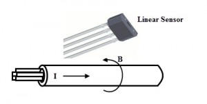
These ICs are fabricated using silicon-CMOS technology in various configurations. The above figure shows the Hall-effect sensor IC of 4 pin package. Out of the total 4 pins, 2 pins are connected to the constant voltage source and other two are connected to the voltmeter.
The arrangement of the connection is shown in figure below. When the magnetic field is absent, the measured voltage across the sheet is negligible.
When the magnetic field is applied at the biased Hall-effect sensor in such a way that the flux lines are right angles to the current flowing through the Hall- element, then the voltage is produced at the output terminals of Hall IC with a magnitude proportional to the magnetic field strength.
Types of Hall-Effect Sensors
Hall-effect sensors need a signal conditioning circuit to make its output usable for many other applications. This signal condition circuit does the amplification, voltage regulation, temperature compensation, linearity, etc. Majorly there are two types of Hall-effect sensors namely analog and bi-level sensors.
Analog Hall-Effect Sensors
These sensors operate over a broader voltage range and also stable in noisy environments as compared with a basic Hall-sensor. The below figure shows the analog output Hall-effect device that produces the analog voltage proportional to the magnetic field to which it is exposed.
The amplifier is provided with a bias or fixed offset so that when the magnetic field is absent that bias voltage is appearing across the output which considered as null voltage. The magnetic field can be either positive or negative at the Hall element.
Hence, the output voltage increases above the null value when the positive magnetic field is sensed while output decreases below the null value when the negative magnetic field is sensed.
With these sensors, the output voltage is within the limits which are imposed by the power supply hence, before reaching the power supply limits, amplifier will start saturates as shown in figure.
It is to be noted that, the saturation occurs in amplifier, but not in Hall-element, therefore there is no damage to the Hall-effect sensors from larger magnetic fields.
Also, these sensors are not quite linear with respect to the magnetic field and hence they need a proper calibration for high precision measurements. Further, by adding push-pull transistor, open-collector, or open emitter to the output of differential amplifier, the interfacing flexibility of the device is increased.
Digital Output Hall-Effect Sensors
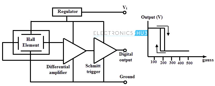
The output of these sensors has two levels: ON or OFF. These sensors also called as bi-level sensors. In addition, the amplifier contains Schmitt trigger with a built-in hysteresis of the threshold level. This Schmitt trigger arrangement converts the analog signal to the digital output by comparing differential amplifier output with fixed reference.
Therefore, when the differential amplifier output is more than the reference or preset value, the Schmitt trigger turns ON while it is falling below the reference value, Schmitt trigger turns OFF.
The two level output signal as function of magnetic field is shown in figure. In this the hysteresis eliminates the avoidable oscillations by introducing dead band zone in which action is disabled after the reference or preset value has passed.
Applications of Hall-Effect Transducers
Depends on the application, Hall-effect sensors are constructed in various configurations. These are very popular measuring devices used in diverse field of applications like industrial process control, biomedical, automobiles, telecommunication, automatic tellers, etc.
These are very widely used as position sensors, liquid level measurement, limit switches and flow measurement. Some of the devices work based on the Hall-effect such as Hall-effect current sensors, Hall-effect vane switches, and Hall-effect magnetic field strength sensors. Some of the applications of the Hall-effect transducers are described below.
Position Sensors
Hall-effect sensors are used for sensing the sliding motion. In this type off sensors there will be a tightly controlled gap between the hall element and the magnet as shown in figure.
As the magnet moves back and forth at a fixed gap, the induced magnetic field will be varied. This field will be negative as the element approaches the North Pole and positive while it approaches the South Pole.
These sensors are also called as proximity sensors which are used for accurate positioning. The figure below shows four digital output bipolar sensors which are threaded into aluminium housing and are actuated by one magnet mounted on a rod.
These sensors generate the signals when magnet moves in acceptable dimensional limits. From a reference surface, these signals represent the distances measured. This type of arrangement is also called as multi position sensing. The best example of such application is the detecting various lens positions for photo processing equipment.
Flow Measurement
The figure below shows the Hall-effect sensor used for measurement of flow. The chamber is provided with a fluid-in and fluid-out openings through which the fluid flows. A spring loaded paddle with a threaded shaft arrangement moves the magnetic assembly to and fro towards the Hall magnet.
As the flow rate increases through the chamber, spring loaded paddle turns the threaded shaft. So the magnetic assembly raises upwards as the shaft turns and hence the transducer get energized.
When the flow rate decreases, then spring coil causes the magnetic assembly to go down. Therefore, the transducer output gets reduced. This whole arrangement is calibrated such that there will be a linear relationship between the measured voltage and flow rate.
Liquid Level Measurement
In this method Hall-effect sensor is used for determining the height of a float thereby the liquid level in the tank is measured. The below figure illustrates an arrangement of float and Hall-effect element or sensor IC in a tank. The float is attached with a magnet such that its actuation varies the magnetic field distance far or near to the Hall-element.
As the liquid level goes up, the magnet moves closer to the sensor and hence the output voltage is increased whereas this voltage decreases when liquid level goes down. So this system provides the simple liquid level measurement without any electrical connections inside the tank.
RPM Sensors
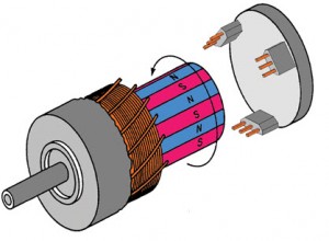
The speed or RPM sensing is the most common application of Hall-effect sensor. In the speed sensing, a Hall-effect sensor is placed stationary in such a way that it face the rotating magnet. This rotating magnet produces the magnetic field required to operate the sensor or Hall-element.
The rotating magnet arrangement can be different ways depends on the convenience of the application. Some of these arrangements are mounting individual magnets on the shaft or hub or by the use of a ring magnet. The Hall sensor gives the output pulses for every time that it faces the magnet.
Further, these pulses are controlled by the processors to determine and display the speed in RPM. These sensors can be either digital or linear analog output sensors.
Brushless DC Motor Sensors
The power distribution of the brushless DC motor is controlled by the electronic commutation instead of the mechanical commutation. Three digital Bipolar Hall effect sensors are placed at the one end of the stator near the pole faces of the rotor to perform the electronic commutation.
For operating these sensors, permanent magnet materials are mounted on the rotor shaft. These sensors measure the position of the rotating magnet so that it determines when the current should be applied to the current to the motor coils to make the magnets rotate in the right direction.
The information sensed by the Hall-effect sensors feed to a logic circuit which further encodes this information and controls the drive circuit. This type feedback mechanism offered by Hall-effect sensors to measure the speed and position of the rotor used for many BLDC motor control applications because of greater flexibility.
Current Sensors
Hall-effect current sensors are used to measure both AC and DC currents. By using the linear analog Hall-effect sensor, it is possible to measure the current ranging from 250 mA to thousands of amperes.
This isolated analog output voltage is further digitized; level shifted and temperature compensated by adding amplifiers.
A current carrying conductor always surrounded by the magnetic field and hence a linear Hall-effect sensor is placed near this field, then a voltage is developed across the output terminal of the sensor as shown in figure. This voltage is proportional to the magnetic field strength around the conductor.
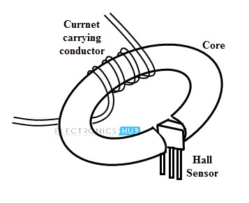
A more sensitive and very efficient isolated current sensing device can be obtained by using Hall-effect sensors in conjunction with an electromagnet. This arrangement consists of a slotted ferrite toroid core with a Hall-effect IC sensor positioned in the gap.
The sensor is enclosed by the core and hence the core acts as a flux concentrator as it focuses the induced magnetic field toward the location where Hall-element is placed as shown in figure.
By varying the number of windings on the core, a few amperes to the thousands of amperes current measurements is possible with this sensor. The output voltage of the Hall-effect sensor is proportional to the current flowing through the windings and hence the current measurement.
Temperature or Pressure Sensors
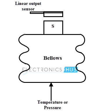
Hall-effect sensors can also be used as pressure and temperature. These sensors are incorporated with a pressure deflected diaphragm with appropriate magnets. A magnetic assembly of a bellows actuates to and fro to the Hall-effect element.
In case of pressure measurement, bellows are subjected to the expansion and contraction. The bellows variation causes to move the magnetic assembly in proximity to the Hall-effect element. Hence the output voltage produced proportional to the pressure applied.
In case of temperature measurement, bellows assembly is sealed with a gas with known thermal expansion properties. When the chamber is heated, the gas inside the bellows gets expanded. This causes a voltage to be produced from sensor proportional to the temperature.


